Sampling apparatus and method for determining the driving state of a vehicle

a technology of driving state and sampling apparatus, which is applied in the field of system for determining the state parameter of an object, can solve the problems of affecting the life of such sensor applications, affecting the operation of the system, so as to achieve the effect of reducing the current consumption, and reducing the cost of operation

Active Publication Date: 2007-12-18
INFINEON TECH AG
View PDF8 Cites 23 Cited by
  • Summary
  • Abstract
  • Description
  • Claims
  • Application Information

AI Technical Summary

Benefits of technology

[0029]It is a further advantage of the present invention that no additional acceleration sensor or motion switch has to be used for detecting the driving state of the vehicle for detecting the driving situation, the evaluation of which leads again to an increased current consumption.
[0030]It is a further advantage of the present invention that data indicating tire pressures can be transmitted regularly and with a minimum frequency, e.g. hourly, to the central unit to allow monitoring of the functionality of the tire pressure sensor for the central unit. The minimum frequency can further be adjusted adaptively so that the data transmission only takes place when, for example, a significant pressure change occurs.
[0031]It is a further advantage of the present invention that the switching threshold (the comparison parameter) is only adapted in the parking state. For tat reason, the inventive switching threshold does not depend on the driving dynamic of the vehicle, the style of driving of the driver, the road and route conditions or the type of tire or tire pressure, but changes merely in dependence on the noise present in a stationary vehicle. This parameter can be easily predicted and depends only on switching properties, whereby a dimensioning of the system is significantly eased, which will lead to cost reduction. Additionally, the inventive system is easier to test since the inventive switching threshold occurs also in a production test under normal environmental pressure and can thus be measured again prior to delivery.
[0032]It is a further advantage of the present invention that merely one switching threshold (a comparison parameter) is used to differentiate between driving state and non-operated state. Apart from a simplification of a circuit complexity, it is achieved that the inventive switching threshold does not depend on individual driving characteristics and vehicle types as well as tire types, but merely on the characteristics of the sensor system which are known during the production of the sensor system and can thus be used for determining plausibility checks, such as minimum and maximum limits of the comparison parameter.
[0033]It is a further advantage of the present invention that a decision, which occurs rarely and which is to be made with high reliability, can be derived from a relatively noisy signal without continuously having to perform an increased number of measurements for noise filtering or without having to set circuit parameters for decreasing the noise, such that, for example, an increased current consumption results. Further, the measurement intervals can be adapted to the maximum allowable decision delays without considering boundary conditions, which the noise of the measurement system dictates, and are only temporarily reduced for a few repetition measurements during exceeding a decision criterion due to noise, which leads to a further reduction of the energy consumption.

Problems solved by technology

If, for example, the measurement data are noisy, there can be wrong decisions in the determination of the state parameter, so that a possible subsequent decision chain based on an erroneously determined state parameter is also erroneous.
Due to the required battery operation of the pressure sensor as well as the transmission unit, the life-span of such sensor applications is limited.
This problem, however, is not only encountered with the already mentioned tire pressure sensors where a time control for measurement and transmission is performed dependent on pressure or acceleration criteria, but also with any battery-operated sensor systems, such as for separately positionable temperature measurement devices.
However, both approaches increase the power consumption, in the first case in proportion to a number of measurement repetitions and in the second case in proportion to oversampling.
With the battery-operated tire pressure sensor configuration, it is not possible to take continuous measurements of the tire pressure measurement values over the whole life-span of the tire pressure sensor configuration, which is in the range of, for example, 10 years.
Common tire pressure sensor configurations have too high a power consumption for that, which limits the life-span of the battery-operated tire pressure sensor configurations, so that a continuous measurement of the physical state parameters, such as pressure or temperature, can not be performed with a sufficiently high measurement repetition rate during the whole intended life-span.
Thus, the relatively high turn-on frequency of the transmission unit in the known tire pressure sensor configurations leads to a relatively high average power consumption of the battery-operated configuration, which has the consequence that the intended life-span of, for example, 10 years, cannot be achieved.
The above-described approach according to the prior art utilizes the fact that dynamic load redistributions occur during a driving operation of the vehicle, which leads to a change of pressure in the tires.
Here, a wrong decision for tranmitting measurement data causes a straining transmission process with high current consumption, while a wrong decision for not transmitting merely causes a short delay of the transmission process.
However, for reliability reasons, these switches are replaced by micromechanical acceleration sensors, the signals of which often have to be read out with the help of amplifiers and / or A / D converters.
Here it applies that an energy consumption of the evaluation circuit increases with increasing demands on accuracy.

Method used


Image

  • Sampling apparatus and method for determining the driving state of a vehicle
  • Sampling apparatus and method for determining the driving state of a vehicle
  • Sampling apparatus and method for determining the driving state of a vehicle

Examples


Embodiment Construction

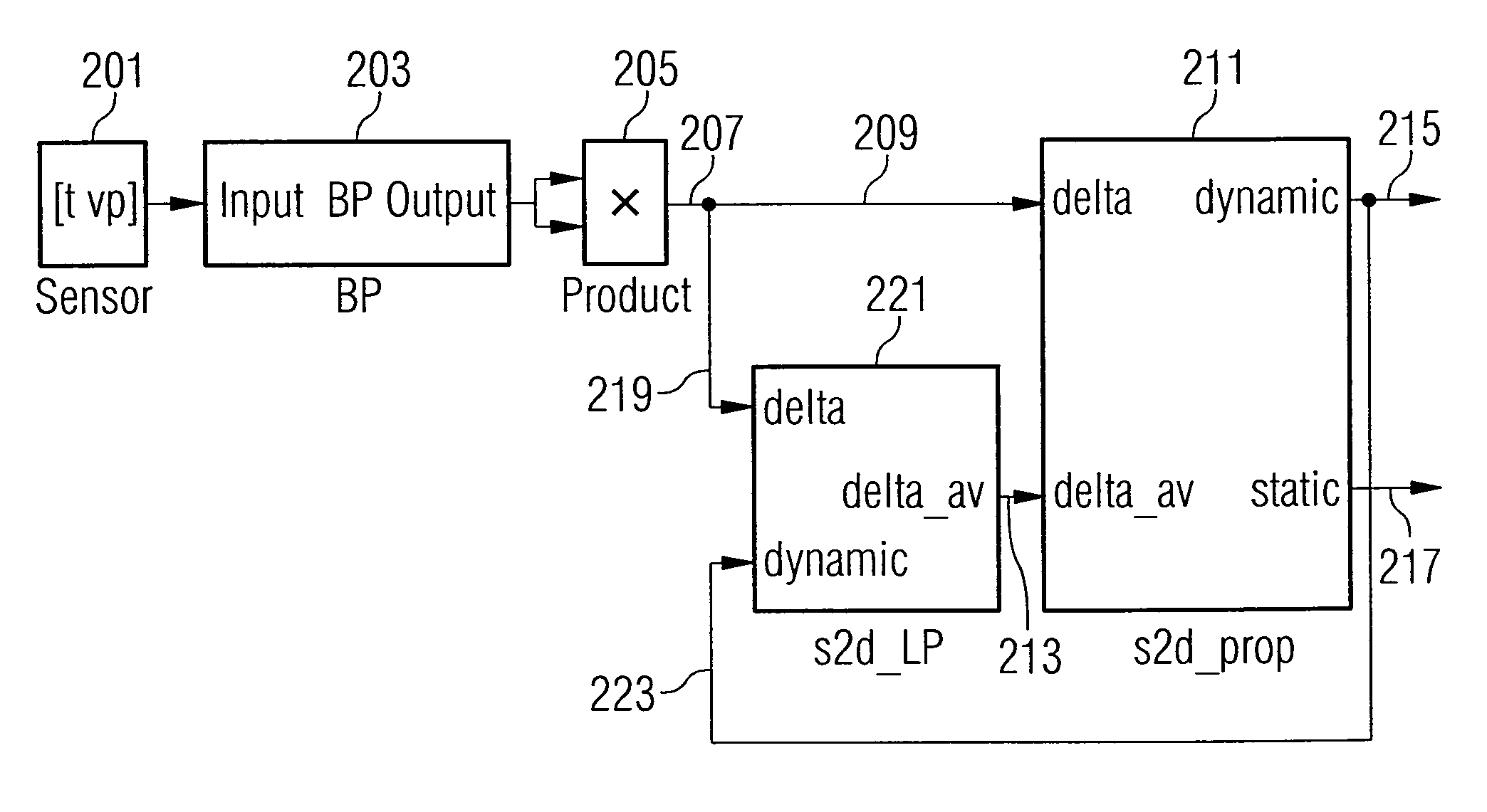
[0043]The apparatus for determining a state parameter of an object to be monitored illustrated in FIG. 1 comprises a means 101 for providing a plurality of measurement values, wherein the measurement values provide information relating to the state parameter of the object to be monitored. The means 101 for providing has an output coupled to an input of a comparison means 103. Further, the comparison means 103 has a further input 105, to which a comparison parameter can be applied, as well as an output 106 for providing a first comparison signal and / or a second comparison signal.

[0044]The comparison means illustrated in FIG. 1 is formed to compare the measurement values provided by the means 101 for providing with a predeterminable comparison parameter. Thereby, the means for comparing 103 is formed to output a first comparison signal when a predeterminable number of measurement values within one measurement interval falls below the comparison parameter, or to output a second compari...


PUM

PropertyMeasurementUnit
timeaaaaaaaaaa
timeaaaaaaaaaa
switching thresholdaaaaaaaaaa

Abstract

An apparatus for determining a state parameter of an object to be monitored comprises a means for providing a plurality of measurement values, wherein the measurement values comprise information relating to the state parameter of the object to be monitored, a comparison means for comparing the measurement value to a predeterminable comparison parameter, wherein the comparison means is formed to output a first comparison signal when a predeterminable number of measurement values falls below the comparison parameter within a measurement interval, or to output a second comparison signal when the predeterminable number of measurement values exceeds or reaches the comparison parameter, wherein the first comparison signal or the second comparison signal indicate the state parameter.

Description

CROSS-REFERENCE TO RELATED APPLICATION [0001]This application claims priority from German Patent Application No. 102004010665.7, which was filed on Mar. 4, 2004 and is incorporated herein by reference in its entirety.BACKGROUND OF THE INVENTION[0002]1. Field of the Invention[0003]The present invention relates to a system for determining a state parameter of an object to be monitored, wherein the state parameter indicates a physical state of the object.[0004]2. Description of the Related Art[0005]In a determination of a state parameter of an object to be monitored, there is often the question of the reliability with which the state parameter has been determined. The state parameter indicating a physical state of the object to be monitored is often determined based on a comparison of measurement data with a threshold. If, for example, the measurement data are noisy, there can be wrong decisions in the determination of the state parameter, so that a possible subsequent decision chain b...

Claims


Application Information

Patent Timeline
Patent Type & Authority Patents(United States)
IPC IPC(8): G06F15/00H04B15/00B60C23/02B60C23/04B60C29/00G01D1/14G01L17/00G05B13/02G05B21/02G08B21/18H03F1/26
CPCB60C23/0474B60C23/0408
Inventor HAMMERSCHMIDT, DIRK
Owner INFINEON TECH AG
Why Eureka
Try Eureka