
Endodontic instruments and method of manufacturing same

a technology of endodontic instruments and manufacturing methods, applied in the field of endodontic instruments and methods of manufacturing endodontic instruments, can solve the problems of instrument failure, instrument self-threading or screwing into the canal, and substantial amount of heat generation, and achieve the effect of rapid and precise manner

Inactive Publication Date: 2007-12-25
INTEGRA YORK PA
View PDF46 Cites 12 Cited by
  • Summary
  • Abstract
  • Description
  • Claims
  • Application Information

AI Technical Summary

Benefits of technology

This method enables rapid, precise manufacturing of endodontic instruments free from heat, stress, and distortions, preserving the original material hardness and preventing self-threading, thus enhancing the durability and effectiveness of the instruments.

Problems solved by technology

The build-up of debris between the flutes of the instrument and the canal walls can cause damage to the canal walls and / or lead to failure of the instrument.
One problem associated with helical fluted endodontic instruments involves the instrument self-threading or screwing into the canal.
This self-threading propensity of helically fluted instruments is a major undesirable operational characteristic that is a leading cause of instrument breakage.
Consequently, a substantial amount of heat is generated, and the instrument may experience mechanical stresses, burrs and other distortions.

Method used


Image

  • Endodontic instruments and method of manufacturing same
  • Endodontic instruments and method of manufacturing same
  • Endodontic instruments and method of manufacturing same

Examples


Embodiment Construction

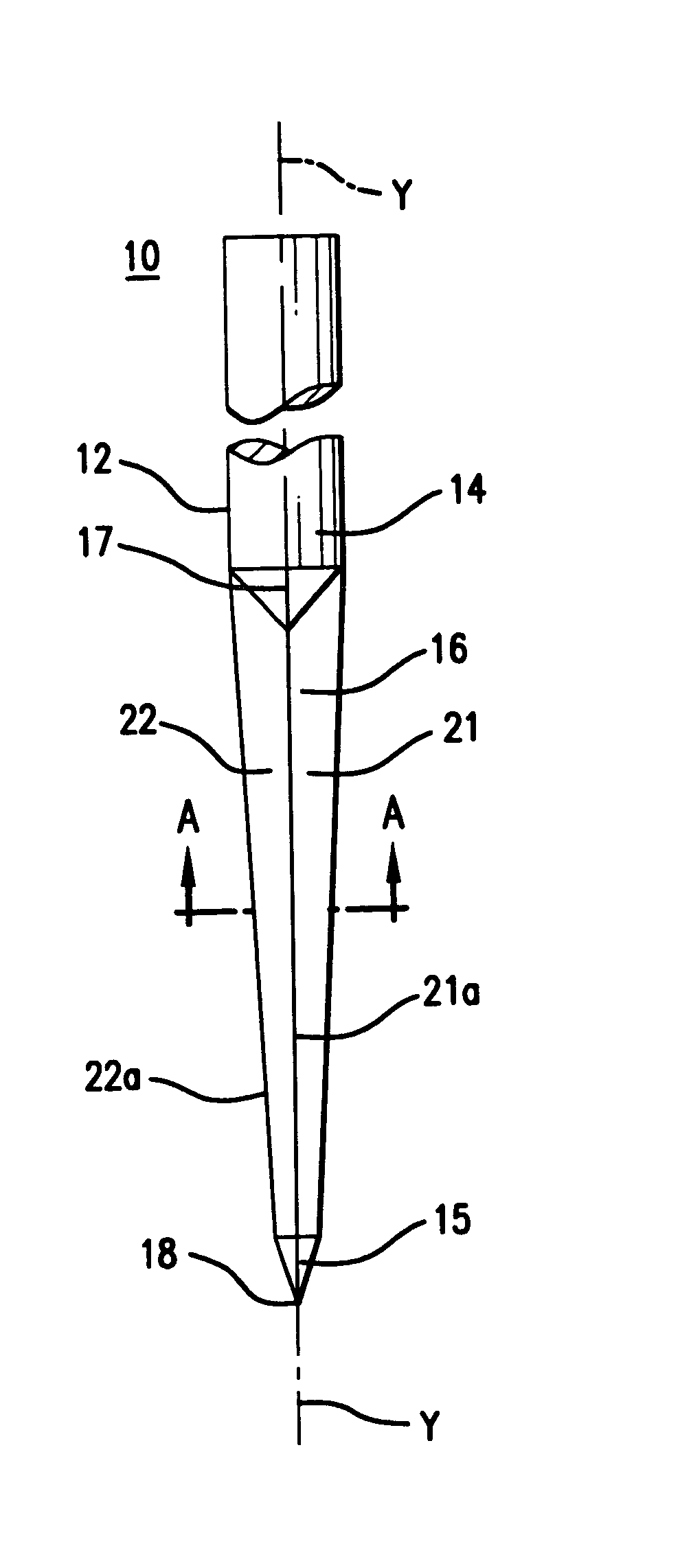
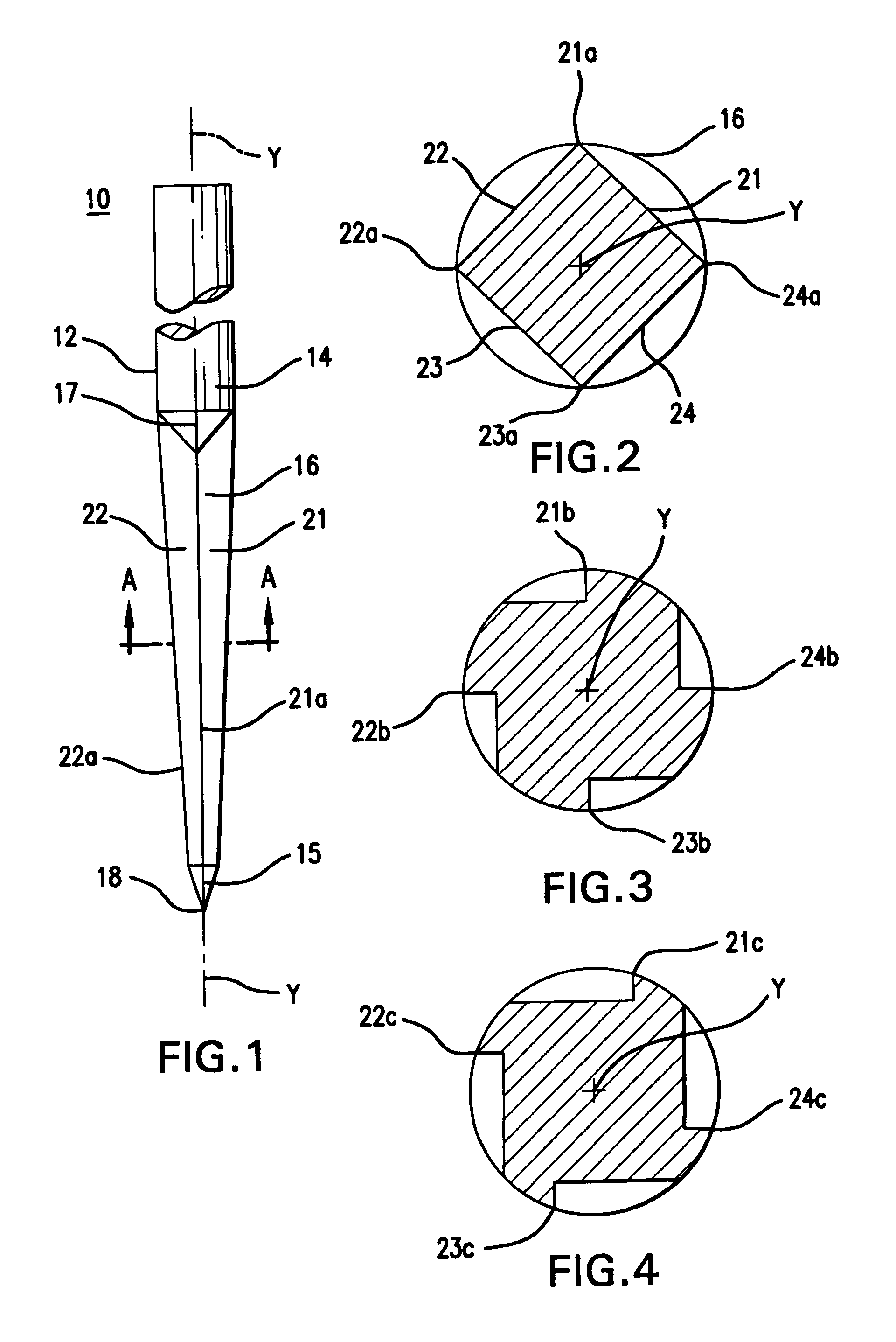
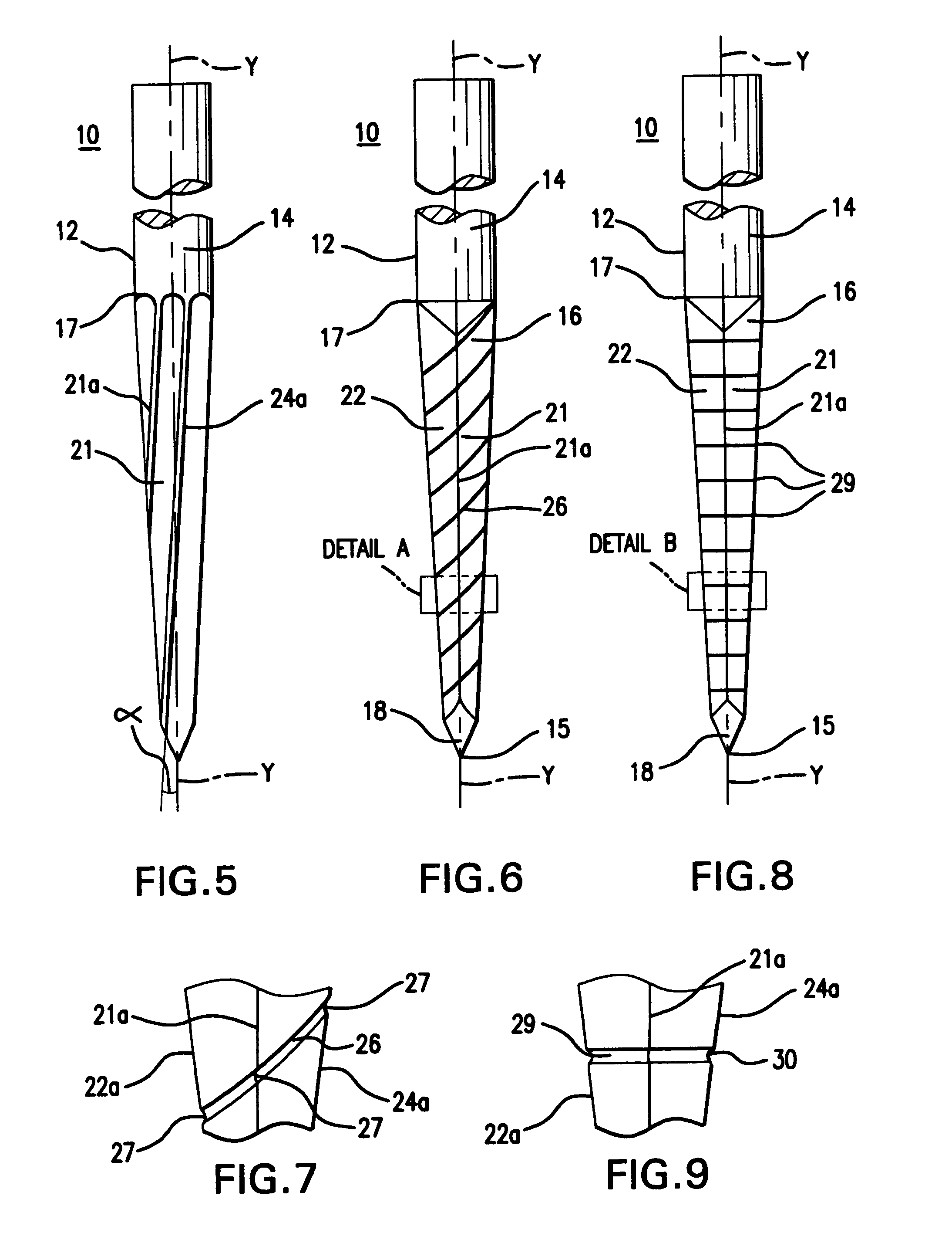
[0036]The present invention relates to an improved endodontic instrument for use in performing root canal therapy on a tooth. In practice, endodontic files and reamers, whether finger manipulated or engine driven, are not normally used in a traditional drill or reamer like fashion. More specifically, endodontic files and reamers are not commonly used in a manner where the instrument is continually rotated in one direction and advanced continuously forward. In reality, finger manipulated files and reamers are quite often used in a watch-winding, quarter-turn-and-pull, or hybrid-balance-force fashion. Engine driven rotary techniques commonly use peck-drill motions, which advance the file or reamer incrementally forward and then retract the instrument. Furthermore, both finger manipulated and engine driven techniques also include repeatedly retracting the file or reamer from the canal to allow irrigation and the introduction of lubricants, which enables debris to be evacuated. Moreover...


PUM

PropertyMeasurementUnit
sizeaaaaaaaaaa
sizeaaaaaaaaaa
angleaaaaaaaaaa

Abstract

A method of manufacturing an endodontic instrument using an electrochemical (ECG) grinding process. An instrument blank is formed from stock material, and an electric current is applied between an electrically conductive grinding wheel, acting as a cathode, and the instrument blank, acting as an anode. A continuous stream of electrolyte fluid, a conductive aqueous solution, is applied at an interface between the grinding wheel and the instrument blank, the electrolyte fluid having an associated volume and pressure. The instrument blank is advanced past the electrically conductive grinding wheel to remove material from the instrument blank to form at least one cutting flute. The electric current applied between the grinding wheel and the instrument blank is reduced, and the instrument blank is advanced past the grinding wheel again to form a finish surface, e.g., a sharp cutting edge, on the at least one cutting flute. The process may be repeated to form an endodontic instrument having a plurality of cutting flutes. The cutting flutes may be helically or non-helically shaped. The instrument blank is formed of an electrically conductive material, such as nickel titanium or stainless steel. In one variation, the electric current may be eliminated entirely during the final finishing pass. The volume and pressure of the electrolyte may be varied. Endodontic instruments formed by the method of the present invention are also disclosed.

Description

CROSS REFERENCE TO RELATED APPLICATIONS[0001]The present application is a continuation-in-part of pending U.S. patent application Ser. No. 10 / 403,400, which was filed on Mar. 31, 2003 and is entitled “Endodontic Instrument.”FIELD OF THE INVENTION[0002]The present invention relates to endodontic instruments and methods of manufacturing endodontic instruments. More particularly, the present invention relates to a method of manufacturing such instruments using an electrochemical grinding (ECG) process.BACKGROUND OF THE INVENTION[0003]When a tooth decays to the point where the inner nerves and roots become infected, dentists must oftentimes perform a root canal procedure in order to save the tooth and prevent further infection. The primary goal of a root canal is to remove all of the decayed or injured nerve while leaving the integrity of the root canal walls relatively unaffected. Preserving the integrity of the root canal is important in order to allow proper filling of the root canal...

Claims


Application Information

Patent Timeline
Patent Type & Authority Patents(United States)
IPC IPC(8): A61C5/02
CPCA61C5/023B24B19/16B24B1/002B23H5/06A61C5/42
Inventor GRAYBILL, LONNIE M.SHEARER, JACK L.LUDWIG, JEFF
Owner INTEGRA YORK PA
Learn More