Plasma method with high input power

a plasma method and input power technology, applied in plasma welding apparatus, manufacturing tools, coatings, etc., can solve the problems of reducing the etching rate, large amount of gas cannot flow, and degenerating etching shapes

Inactive Publication Date: 2007-12-25
FOUND FOR ADVANCEMENT OF INT SCI
View PDF16 Cites 29 Cited by
  • Summary
  • Abstract
  • Description
  • Claims
  • Application Information

AI Technical Summary

Benefits of technology

[0013]a container, the inside of which can be internally decompressed, and part of the inside being formed of a first dielectric plate made of material capable of passing microwaves with almost no loss,
[0020]A plasma processing method of the present invention is a method using a plasma device comprising a container, the inside of which can be internally decompressed, and part of the inside being formed of a first dielectric plate made of material capable of passing microwaves with almost no loss, a gas supply system for supplying essential source material gas so as to cause excitation of plasma inside the container, an exhaust system for expelling source material gas that has been supplied inside the container and decompressing the inside of the container, an antenna, located facing an outer surface of the first dielectric plate and comprised of a slot plate and a waveguide dielectric, for radiating microwaves, and an electrode for holding an object to be treated located inside the container, a surface of the object to be treated that is to be subject to plasma processing and a microwave radiating surface of the antenna being arranged in parallel substantially opposite to each other, and the plasma device carrying out plasma processing for the object to be treated, the power density of microwaves to be input being 1.2 W / cm2 or more. This method assures stable generation of plasma.
[0025]a container, the inside of which can be internally decompressed, and part of the inside being formed of a first dielectric plate made of material capable of passing microwaves with almost no loss,

Problems solved by technology

Since the gas is made to flow uniformly in a direction of rotation of the space above the substrate 4303, the gas conductance between the space above the substrate 4303 and the gas outlet 4311 is inevitably restricted and there is a problem that a large amount of gas can not flow.
As a result, in high speed etching on large diameter substrates the etching rate is lowered, and a problem arises that the etching shape degenerates.
At the time of plasma generation, power loss occurs due to high frequency current flowing in the bellows 4307, and there is a problem that the high frequency output power of the high frequency power source 4314 can not be efficiently supplied to the plasma.
There is also a problem that a complex structure is required because the electrode I 4302 is made to move.
This device enables excitation of high density uniform plasma on a substrate, but since the method involves high density plasma being excited locally, caused to widely diffuse within the container and uniformly supplied onto a object to be treated, installation of a shower plate is difficult, and it is difficult to promptly remove gases that are reaction by-products.
However, if this device is put to practical use, it is not always possible to cause high density plasma to be generated stably over a long period of time.
Also, the conditions for causing the generation of plasma are not definite.

Method used


Image

  • Plasma method with high input power
  • Plasma method with high input power
  • Plasma method with high input power

Examples


embodiment 1

[0351](Embodiment 1)

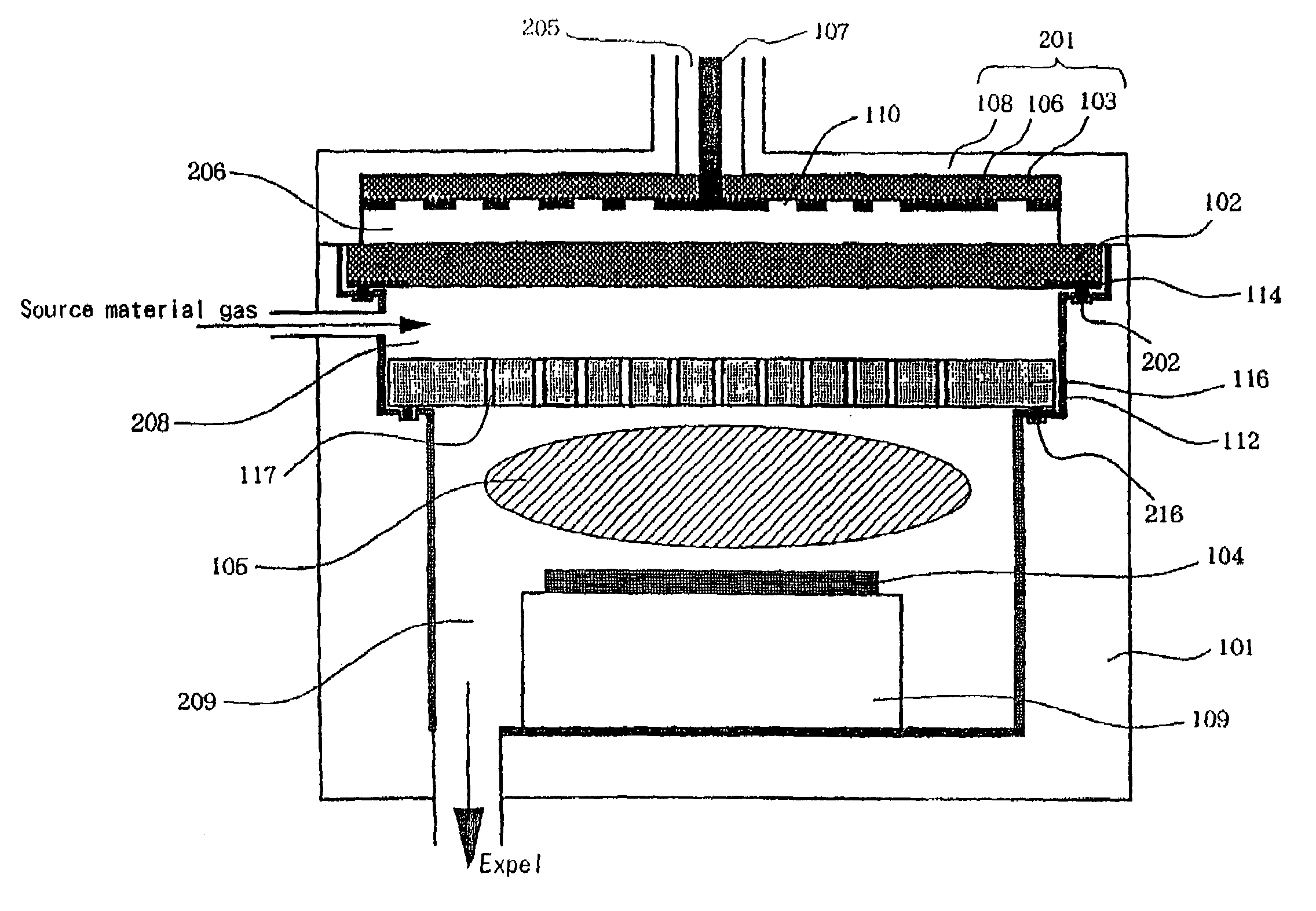
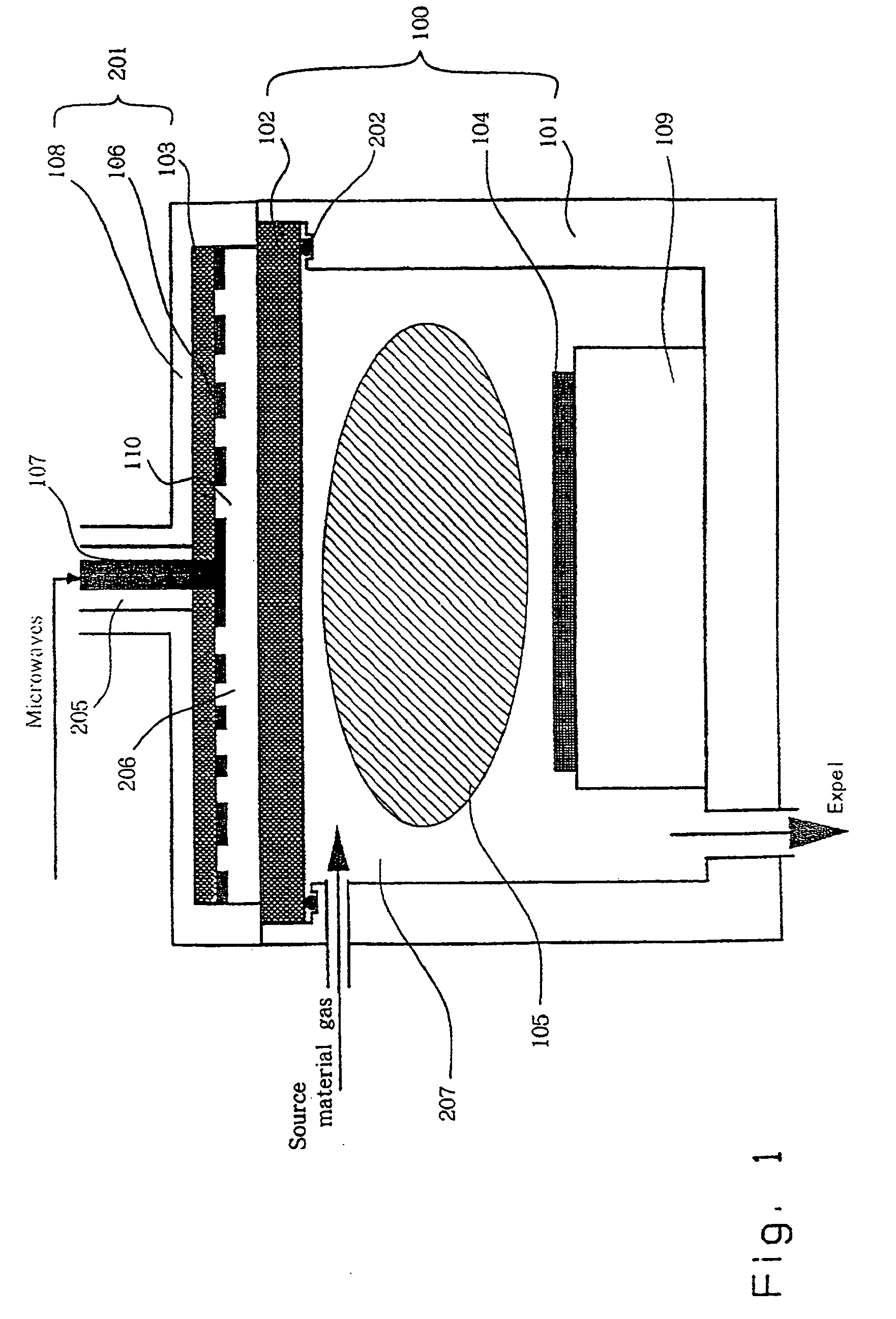
[0352]In this embodiment, when plasma is generated by introducing microwaves into a container using the plasma device shown in FIG. 1, the plasma stability is examined by varying the material of a member constituting an inner surface of the container, and the width of the member.

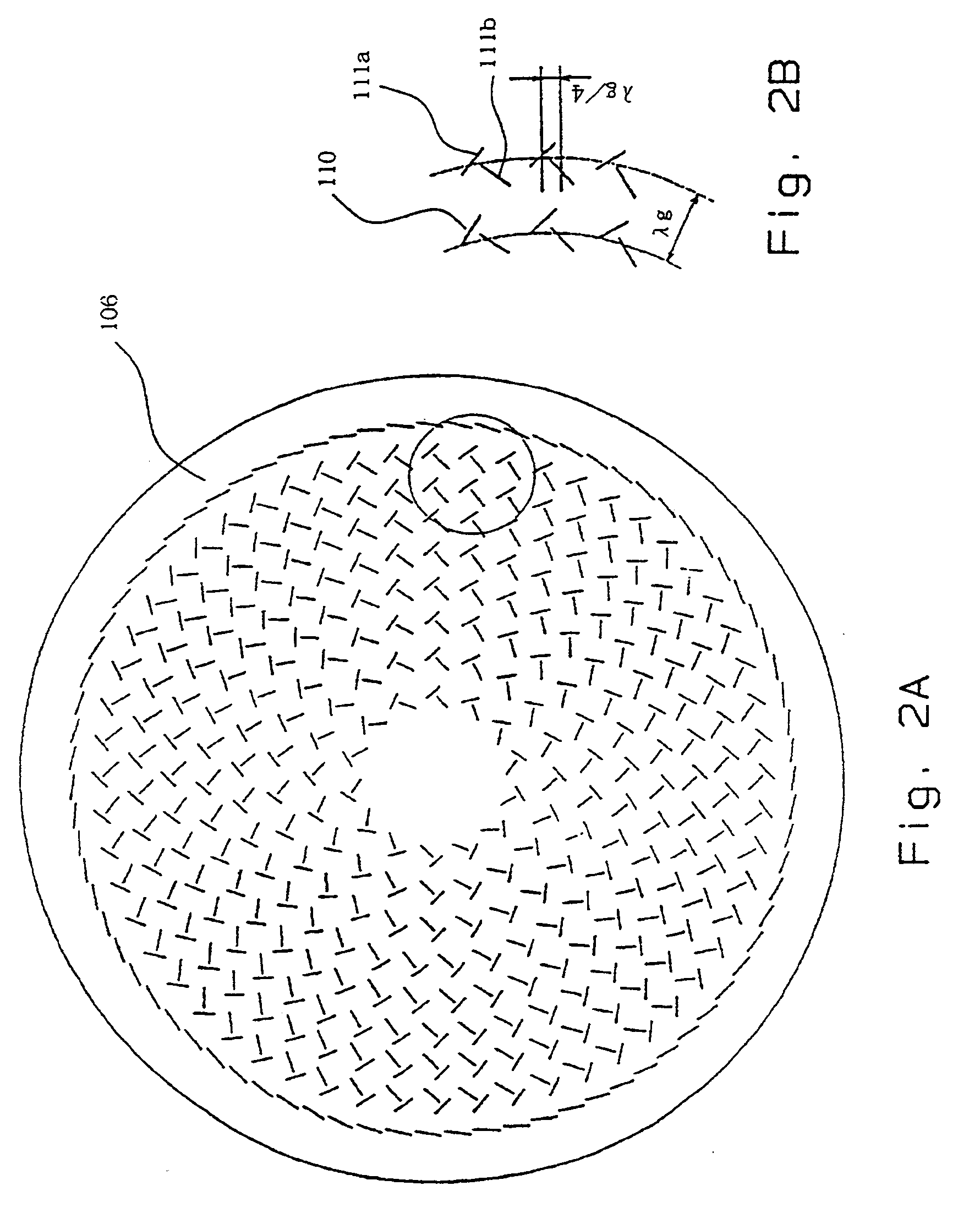
[0353]In FIG. 1, reference numeral 100 is a container capable of having its internal pressure reduced, reference numeral 101 is a chamber, reference numeral 102 is a first dielectric plate, reference numeral 103 is a waveguide dielectric plate, reference numeral 104 is an object to be treated, reference numeral 105 is plasma, reference numeral 106 is an antenna slot plate, reference numeral 107 is a coaxial tube, reference numeral 108 is an antenna guide, reference numeral 109 is an electrode, reference numeral 110 is a slot, reference numeral 201 is a radial line slot antenna, reference numeral 202 is a first O ring, reference numeral 205 is a space 3, reference numeral 206 is a space 4 ...

embodiment 2

[0372](Embodiment 2)

[0373]In this embodiment, the device of FIG. 5 is different from embodiment 1 in that a metallic thin film 114 is provided at a vacuum seal region where the first dielectric plate 102 (material: quartz) contacts a first O ring 202, as shown in FIG. 7, and the first O ring is not exposed to electromagnetic waves radiated from the antenna slot plate 106. Fluorine type resin is used as the material for the first O ring.

[0374]FIG. 8 is an enlarged view of region A in FIG. 7, and shows the case where the metallic thin film 114 is provided at a vacuum seal region where the first dielectric plate 102 (material: quartz) contacts a first O ring 202.

[0375]When the first O ring is made of a material such as resin that absorbs microwaves, it is directly heated by electromagnetic waves radiated from the antenna slot plate 106m as a result of discharge over a long time and it will be understood that damage will occur.

[0376]Therefore, metallic thin films each having a thickness...

embodiment 3

[0379](Embodiment 3)

[0380]In this embodiment, as shown in FIG. 10, a device provided with a second dielectric plate 116, having a gas inlet 117 for supplying desired gas in a substantially uniform manner provided between the first dielectric plate 102 and the electrode 109 for holding the object to be treated 104, was used, and the uniformity of plasma 105 generated in the space 2 (109) was examined.

[0381]FIG. 10 shows the device incorporating the results of the second embodiment, and aluminum (Al) was coated to a thickness of 10 μm as a metallic thin film 114, at a region for vacuum sealing where the first dielectric plate 102 comes into contact with the first O ring 202. AlN (aluminum nitride) was used as the second dielectric plate 116 shown in FIG. 10. Since aluminum nitride contains nitrogen, it is characterized by the fact that there is less discharge gas compared to quartz.

[0382]In the device of FIG. 10, Ar gas was introduced into space 1 (208) as a plasma gas, and uniformity...


PUM

PropertyMeasurementUnit
electron densityaaaaaaaaaa
thicknessaaaaaaaaaa
specific conductivityaaaaaaaaaa

Abstract

A plasma device which is provided with a container, a gas supply system, and an exhaust system. The container is composed of a first dielectric plate made of a material capable of transmitting microwaves. An antenna for radiating microwaves is located on the outside of the container, and an electrode for holding an object to be treated is located inside the container. The microwave radiating surface of the antenna and the surface of the object to be treated with plasma are positioned in parallel and opposite to each other. A wall section of the container other than that constituting the first dielectric plate is composed of a member of a material having electrical conductivity higher than that of aluminum, or the internal surface of the wall section is covered with the member. The thickness (d) of the member is larger that (2 / μ0σ)1 / 2, where σ, μ0 and ω respectively represent the electrical conductivity of the member, the permeability of vacuum and the angular frequency of the microwaves radiated from the antenna.

Description

CONTINUATION DATA[0001]This is a divisional of U.S. patent application Ser. No. 10 / 100,533, filed on Mar. 18, 2002, which is a divisional of patent application Ser. No. 09 / 355,229 filed on Oct. 5, 1999 now U.S. Pat. No. 6,357,385, the disclosure of each of which is herein explicitly incorporated by reference.BACKGROUND OF THE INVENTION[0002]1. Field of the Invention[0003]The present invention relates to a plasma device.[0004]2. Description of the Related Art[0005]Recently, accompanying the increase in chip size of ULSI (ultra large scale integrated circuits), there has also been a tendency to increase the diameter of a silicon substrate used as a substrate for the ULSI. Since sheet leaf processing for handling substrates one at a time has become mainstream, if the substrate is increased in diameter there is a need for high speed processing of at least 1 mm per minute in order to maintain high productivity if etching and film forming are carried out. In a plasma device for handling a...

Claims


Application Information

Patent Timeline
Patent Type & Authority Patents(United States)
IPC IPC(8): B23K10/00C23C16/511H01J37/32H01L21/302H01L21/316
CPCC23C16/511H01L21/31691H01J37/32238H01J37/3244H01L21/02115H01L21/0212H01L21/02129H01L21/02164H01L21/0217H01L21/02197H01L21/02238H01L21/02247H01L21/02252H01L21/02274H01L21/31612H01L21/31625H01L21/31675H01J37/32192
Inventor OHMI, TADAHIRONITTA, TAKAHISAHIRAYAMA, MASAKITAKANO, HARUYUKIKAIWARA, RYU
Owner FOUND FOR ADVANCEMENT OF INT SCI
Why Eureka
Try Eureka