Image display apparatus and method

a technology of image display and display device, which is applied in the direction of instruments, television systems, static indicating devices, etc., can solve the problems of not reproducing detailed information, unable to evaluate an object as a full-scale object in real space,

Active Publication Date: 2007-12-25
CANON KK
View PDF9 Cites 48 Cited by
  • Summary
  • Abstract
  • Description
  • Claims
  • Application Information

AI Technical Summary

Problems solved by technology

However, the method of displaying three-dimensional CAD data on a computer screen as a 3D-CG merely allows evaluation in virtual space, and it is impossible to evaluate an object as a full-scale object in real space.
Furthermore, the method of generating a simple prototype (simple mockup) by a rapid prototyping device is effective for grasping a rough shape of an object under the constraints of processing precision, materials and so on, but it does not reproduce detailed information, e.g., the detailed design and shape, colors and so on, designed by the 3D-CAD.

Method used


Image

  • Image display apparatus and method
  • Image display apparatus and method
  • Image display apparatus and method

Examples


first embodiment

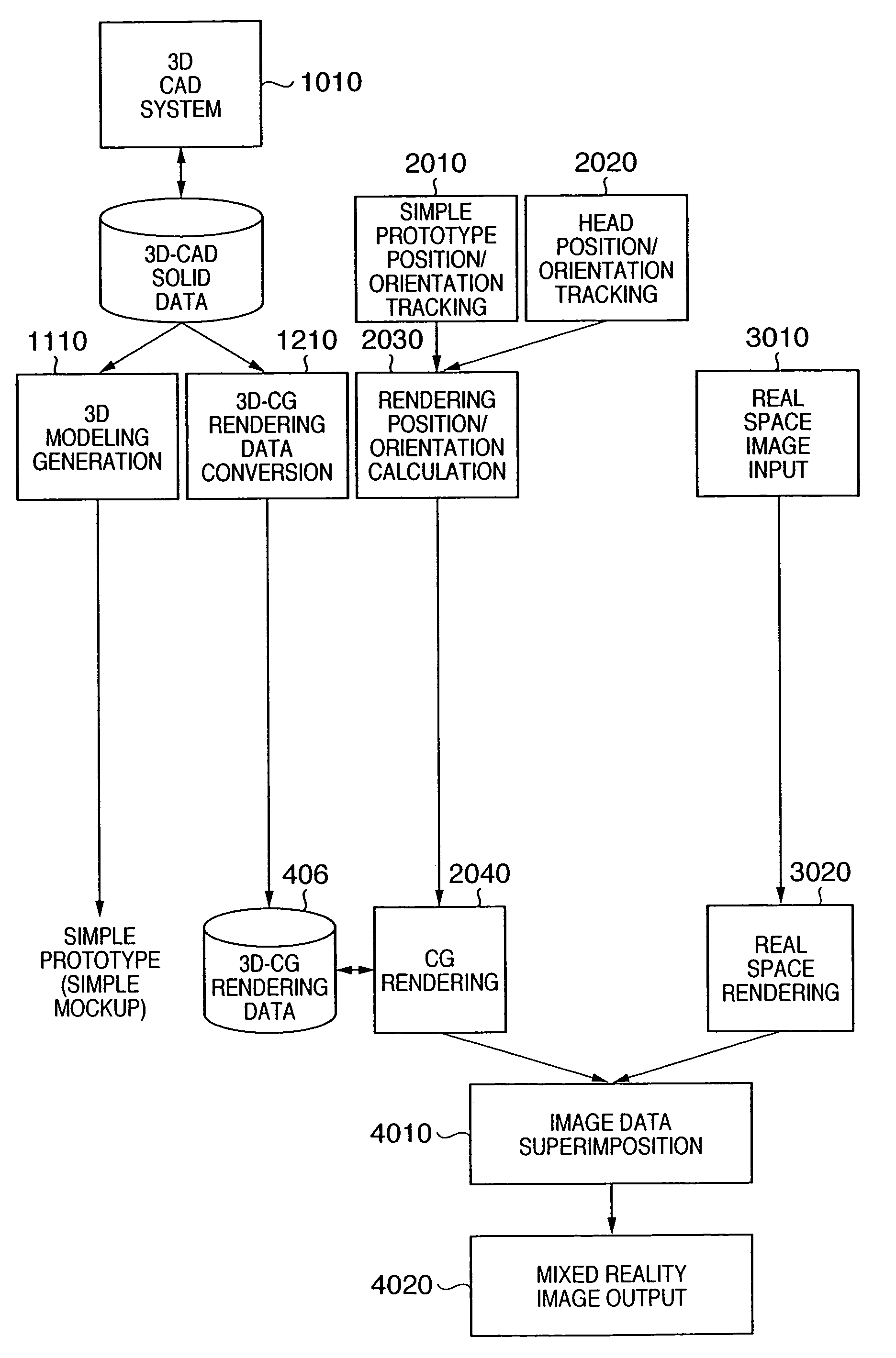
[0028]In the mixed reality system according to the first embodiment which will be described below, a photographed image of a simple prototype (simple mockup), which is generated by a rapid prototyping device based on three-dimensional CAD data, is superimposed on three-dimensional CG (3D-CG) data generated by converting the same three-dimensional CAD data, and their positions and orientations are matched and displayed in the mixed reality system. This system realizes both visual evaluation and tactual evaluation, thus enabling evaluation under the condition close to a finished product.

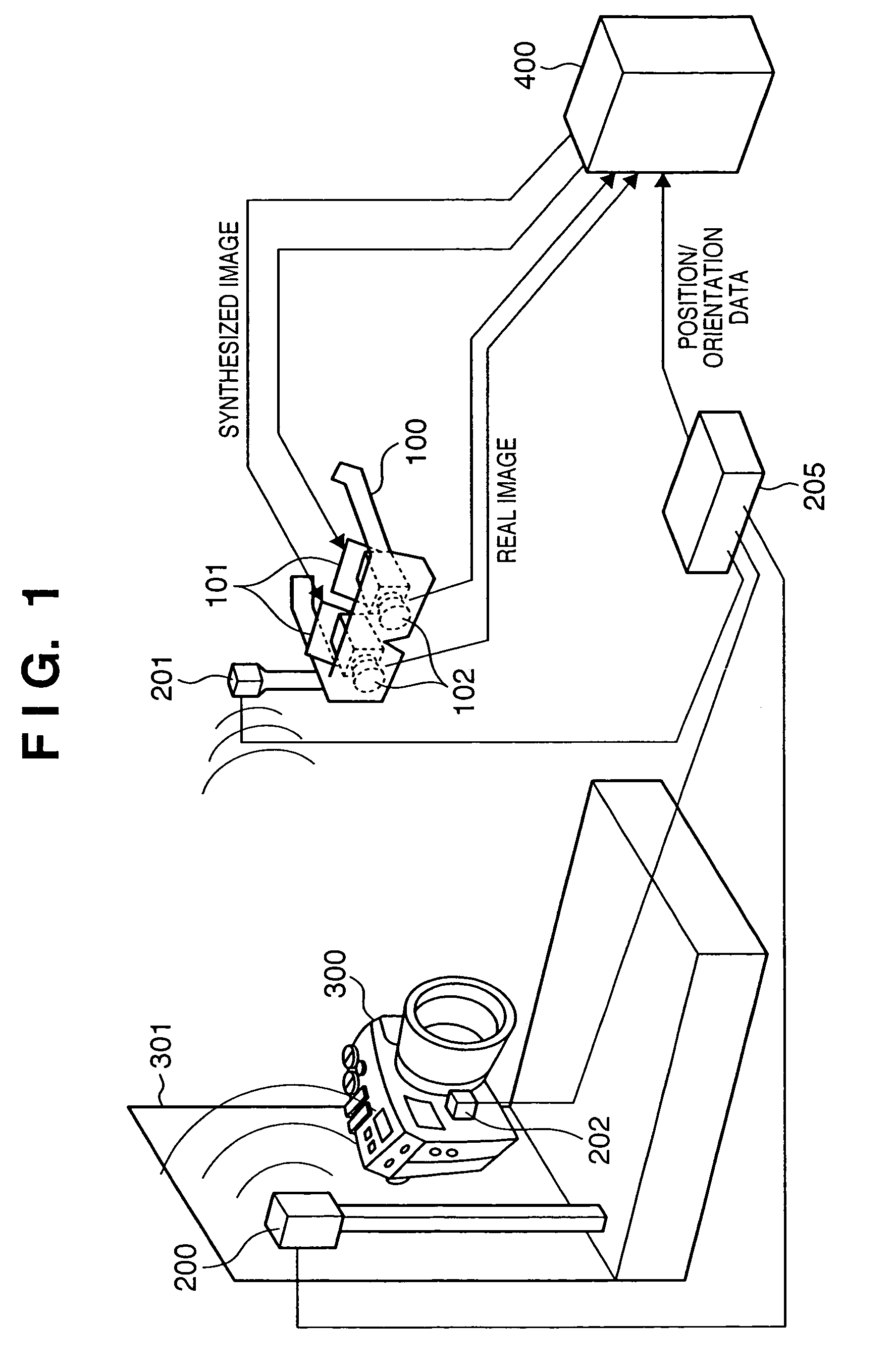
[0029]The construction of the system according to the first embodiment is shown in FIG. 1.

[0030]Referring to FIG. 1, numeral 100 denotes a head mounted type image input / output device (called head mounted display (HMD)), which is mounted to the viewer's head for viewing a synthesized image of real space and virtual space. Numeral 200 denotes a magnetic transmitter which generates a magnetic field; and 2...

second embodiment

[0048]The first embodiment has described, as an example, position orientation tracking using magnetism. However, in the position / orientation tracking using magnetism, the tracking precision may become unstable depending on the environment. For instance, if a metal object exists near the magnetic transmitter, the magnetic field is disturbed, resulting in an unstable output value of the magnetic sensor. Furthermore, there is a problem in that, the larger the distance between the magnetic transmitter and the magnetic sensor, the more the tracking precision is deteriorated. Such problem regarding tracking precision is not limited to sensors using magnetism, but occurs in a position / orientation tracking device using various methods. For instance, in a case of optical position / orientation tracking means, there is a problem in that if a shielding object exists between a light emitting device and a light receiving device, the tracking becomes unstable, causing an error.

[0049]In view of this...

third embodiment

[0066]In the above-described first and second embodiments, the image synthesizing unit 402 superimposes (overwrites) the virtual space image (CG image) data on the real space image data, thereby generating a synthesized image. In this case, because an object that is supposed to be in front of the CG image is overwritten by the CG image, a contradiction occurs between the depth representations of a CG image and a real object. The contradiction is described in detail with reference to FIGS. 10A to 10D.

[0067]FIG. 10A shows an example of real space image data inputted by the image input device 102, which is a simple prototype held by viewer's hands. A part of the hands (thumbs) is shown in front of (before) the prototype. If a CG image corresponding to the simple prototype is superimposed on this image, a synthesized image shown in FIG. 10B is displayed. In other words, the part of the hands that should exist in front of (before) the simple prototype is hidden by the CG image, causing c...


PUM


Abstract

Image display method of superimposing virtual space image data on real space image data at an arbitrary viewpoint and exhibiting the superimposed image to a viewer is provided. When real space image data, including a prototype generated based on three-dimensional CAD data, is captured by an image sensing device, the position and orientation of the image sensing device and the prototype are tracked, and position / orientation data indicative of the position and orientation of the prototype in the image is acquired. Based on the position / orientation data and the three-dimensional CAD data, a three-dimensional computer graphic image is rendered so as to overlap the prototype in the image, thereby synthesizing the image with the three-dimensional computer graphic image. The synthesized image is then displayed.

Description

FIELD OF THE INVENTION[0001]The present invention relates to an image display apparatus and method employed in a mixed reality system, which exhibits a viewer image data in virtual space superimposed on image data in real space at an arbitrary viewpoint.BACKGROUND OF THE INVENTION[0002]The mixed reality system provides a user with a synthesized image, which is obtained by synthesizing a real space image with a virtual space image generated in accordance with a user's viewpoint position, visual line direction, and so forth. The mixed reality system can give a viewer a sense that as if a virtual object really exists in real space. Compared to a conventional virtual reality system (VR system), more realistic and full-scale viewing is possible (refer to Japanese Patent Application Laid-Open No. 11-136706).[0003]Meanwhile, in the design and production field, designing (shapes and designs) by a three-dimensional CAD is prevailing. The mainstream method of evaluating an object designed by ...

Claims


Application Information

Patent Timeline
Patent Type & Authority Patents(United States)
IPC IPC(8): G06T15/00G06T7/00H04N5/222
CPCG06T7/0042G06T19/006H04N5/222H04N5/275H04N13/044H04N13/0468H04N5/272H04N5/2224G06T7/73H04N13/344H04N13/366
Inventor ASO, TAKASHISATO, HIROAKISUZUKI, MASAHIRONAKAZAWA, TOSHIHIRO
Owner CANON KK
Why Eureka
Try Eureka