
Electronics equipment cabinet

a technology for electronics equipment and cabinets, applied in the field of equipment cabinets, can solve the problems of reducing the operating performance and reducing the life of the equipment, and the newer generation equipment dispersing more heat during operation, so as to reduce solar load, attenuate the noise emitted by the one, and reduce the noise generated by the fans

Inactive Publication Date: 2007-12-25
WSOU INVESTMENTS LLC
View PDF10 Cites 57 Cited by
  • Summary
  • Abstract
  • Description
  • Claims
  • Application Information

AI Technical Summary

Benefits of technology

The solution effectively attenuates fan noise, improves thermal management by enhancing heat transfer efficiency, and reduces solar loading, ensuring optimal performance and compliance with noise emission limits while maintaining efficient cooling for high-power electronics equipment.

Problems solved by technology

As a result, this newer generation equipment dissipates more heat during operation than older generation equipment.
Dissipating heat from electronics equipment is important as excess operating temperatures may decrease the operating performance and life-span of the equipment.
However, such natural convection cooling techniques are typically not sufficient to provide the cooling needed to promote optimal performance of newer generation electronics equipment.
However, the fans used in such equipment often generates excessive noise.
This is problematic as noise emission limits for electronics equipment cabinets installed in the field are being routinely lowered.

Method used


Image

  • Electronics equipment cabinet
  • Electronics equipment cabinet
  • Electronics equipment cabinet

Examples


Embodiment Construction

[0029]In the following description, details are set forth to provide an understanding of the invention. In some instances, certain circuits, structures and techniques have not been described or shown in detail in order not to obscure the invention.

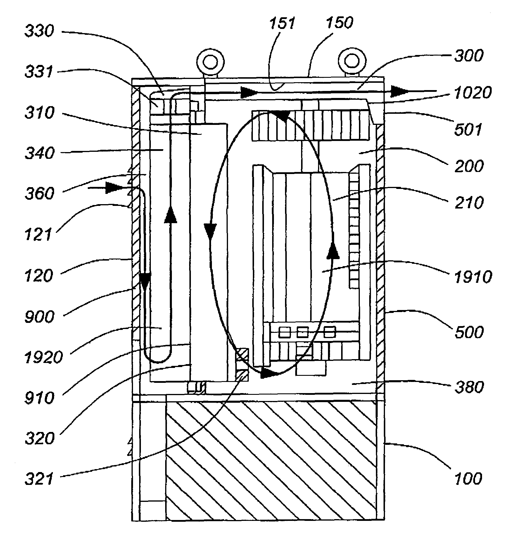
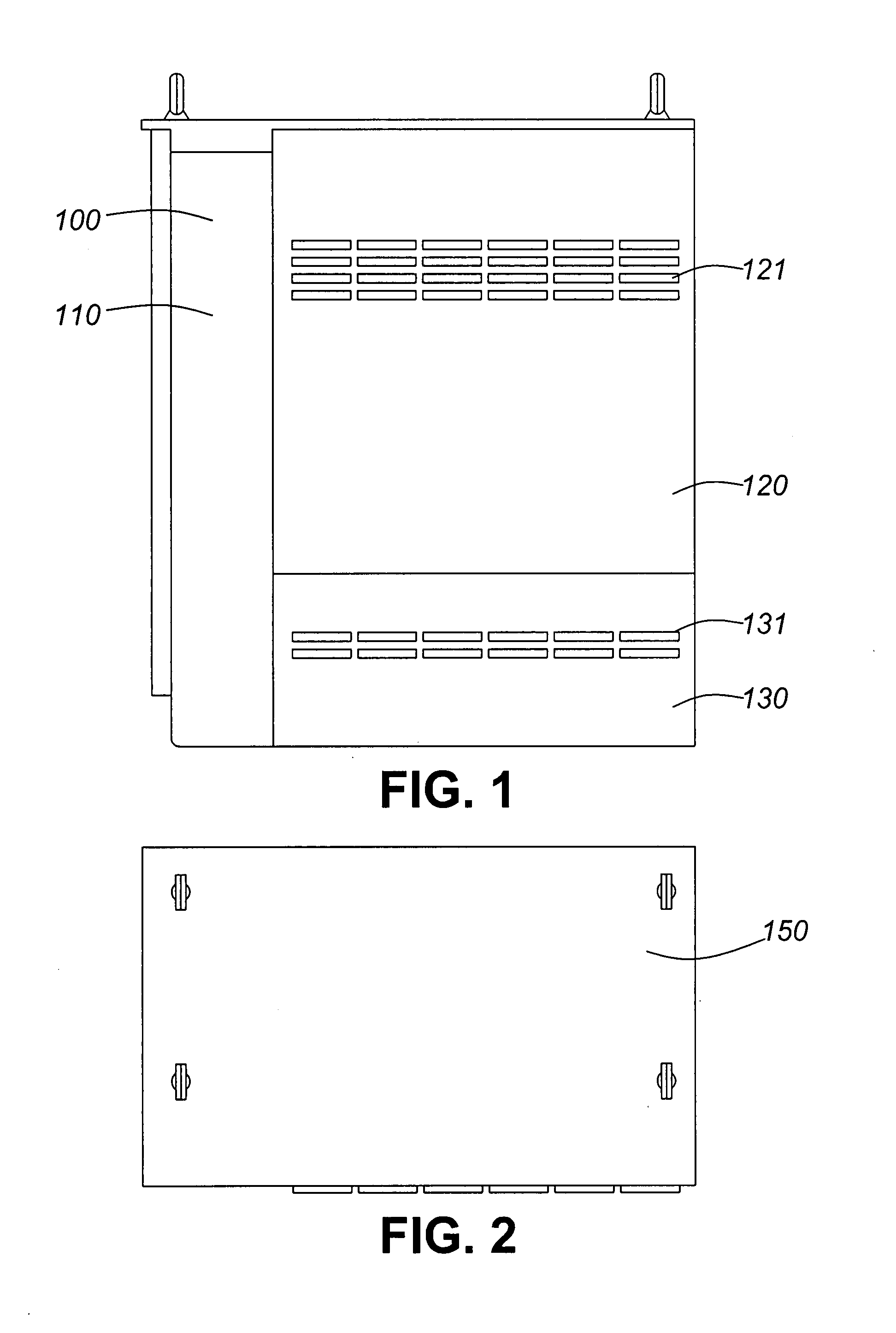
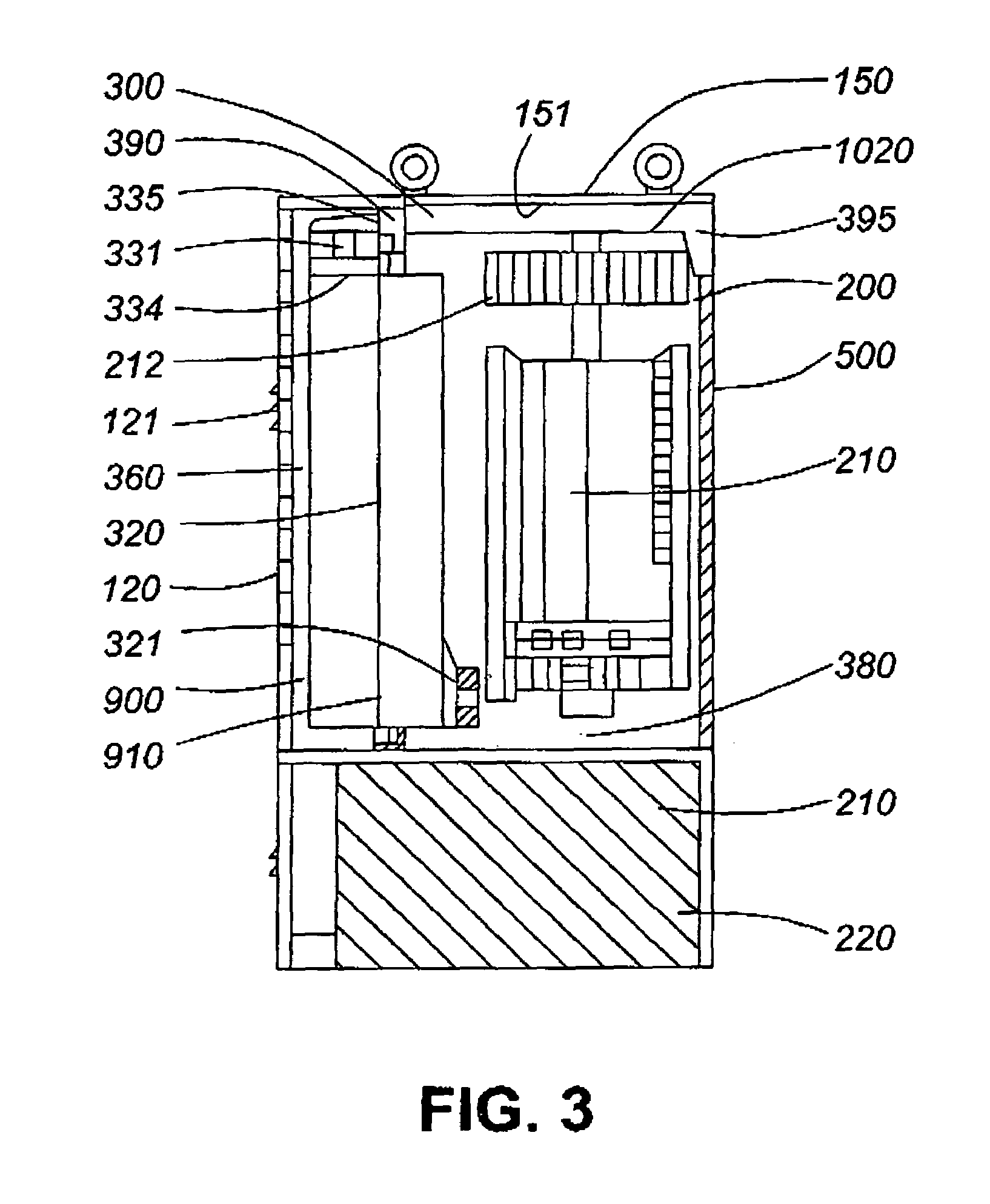
[0030]FIG. 1 is a front view illustrating an electronics equipment cabinet 100 in accordance with an embodiment of the invention. FIG. 2 is a top view of the cabinet 100. FIG. 3 is a section view of the cabinet 100 (along line A-A in FIG. 1). FIG. 4 is a front perspective view of the cabinet 100. FIG. 5 is a rear perspective view of the cabinet 100. FIG. 6 is a front perspective exploded view of the cabinet 100. FIG. 7 is a front view (doors and panels removed) of the cabinet 100. And, FIG. 8 is a left side view (doors and panels removed) of the cabinet 100.

[0031]Referring to FIGS. 1-8, the cabinet 100 has a frame or housing 110 in which is formed an electronics equipment compartment 200, a battery compartment 220, a splice compartment 600...


PUM


Abstract

A cabinet for electronics equipment, comprising: a compartment for installing the electronics equipment; a door for accessing the compartment; an outer duct mounted on an outer surface of the door for directing exterior air around a heat exchanger core mounted in the door, the heat exchanger core for transferring heat from interior air in the compartment to the exterior air to thereby cool the interior air; an exhaust duct extending over a top surface of the compartment and pneumatically coupling with the outer duct when the door is in a closed position, the exhaust duct for exhausting the exterior air and for reducing solar loading on the top surface by transferring heat absorbed by the exhaust duct to the exterior air passing therethrough; and, one or more fans for forcing the exterior air in through the outer duct, around the heat exchanger core, and out through the exhaust duct, the one or more fans being mounted between the outer duct and the exhaust duct to thereby attenuate noise emitted by the one or more fans.

Description

FIELD OF THE INVENTION[0001]This invention relates to the field of equipment cabinets, and more specifically, to cabinets for electronics equipment.BACKGROUND OF THE INVENTION[0002]The power requirements of electronics equipment (e.g., telecommunications equipment) is continually increasing. In particular, newer generation telecommunications equipment has increased power density. That is, the power requirements of such equipment per unit volume has increased. As a result, this newer generation equipment dissipates more heat during operation than older generation equipment. Dissipating heat from electronics equipment is important as excess operating temperatures may decrease the operating performance and life-span of the equipment. As such, electronics equipment installed in cabinets require sufficient cooling to ensure optimal operating performance and life-span. This is especially so for electronics equipment cabinets that are weatherproofed for outdoor use.[0003]Several existing e...

Claims


Application Information

Patent Timeline
Patent Type & Authority Patents(United States)
IPC IPC(8): H05K7/20
CPCH05K7/206
Inventor BUNDZA, NICHOLAS ADAMDE CECCO, STEFANOARLOTTA, ANGELO
Owner WSOU INVESTMENTS LLC
Learn More