Trunking in a matrix

a matrix and matrix technology, applied in the field of matrix truncation, can solve problems such as unnecessary matrix traffic, and achieve the effect of reducing unnecessary traffi

Inactive Publication Date: 2007-12-25
CONVERSANT INTPROP MANAGEMENT INC
View PDF23 Cites 37 Cited by
  • Summary
  • Abstract
  • Description
  • Claims
  • Application Information

AI Technical Summary

Benefits of technology

[0024]FIG. 11 illustrates an example of local echo suppression tables for reducing unnecessary traffic through the matrix for received unicast frames.

Problems solved by technology

Thus, a frame may be needlessly forwarded throughout the matrix of switch devices before being forwarded to the selected member of the trunk group, resulting in unnecessary traffic in the matrix.

Method used


Image

  • Trunking in a matrix
  • Trunking in a matrix
  • Trunking in a matrix

Examples


Embodiment Construction

[0025]A description of preferred embodiments of the invention follows.

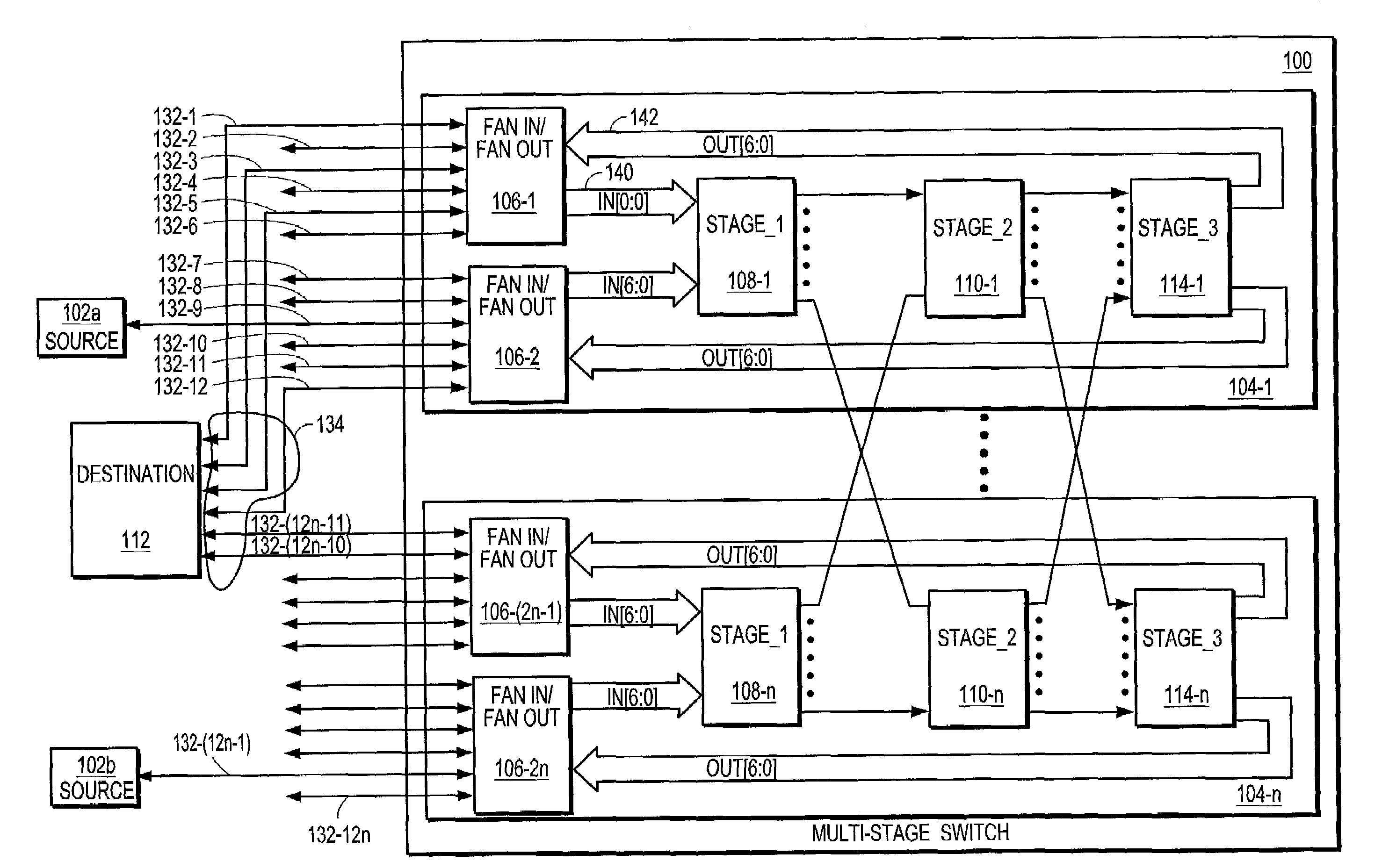
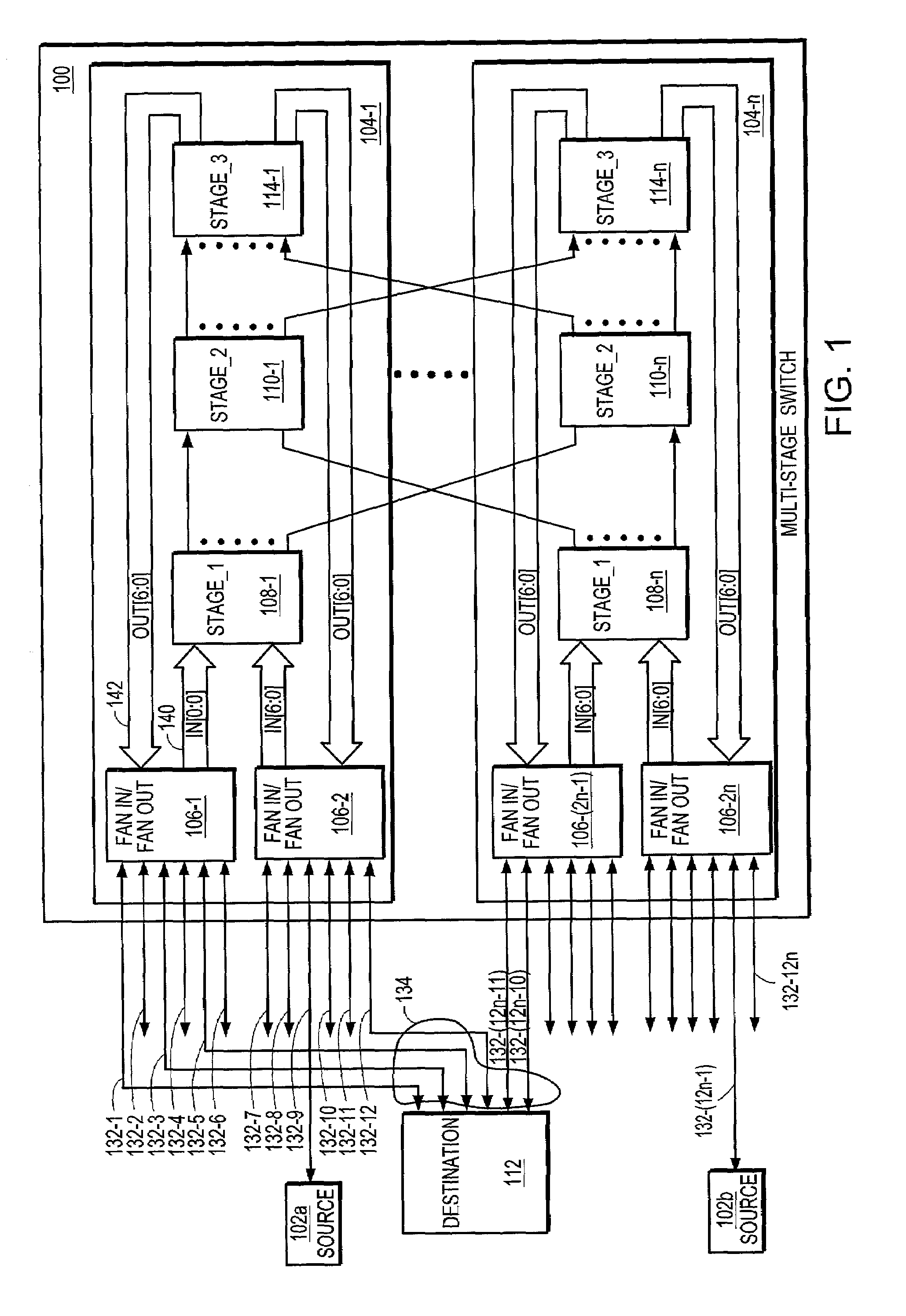
[0026]FIG. 1 illustrates a logical link or trunk group 134 connecting a destination 112 to a multistage switch 100 according to the principles of the present invention. The multistage switch 100 includes a matrix of coupled switch devices 106-1, . . . 106-2n, 1081, . . . 108-n, 110-1, . . . 110-n, 114-1, . . . 114-n organized in rows and columns. Each row 104-1, . . . 104-n includes five switch devices. As shown, row 104-1 includes two fan in / fan out devices 106-1, 106-2, a stage-1 device 108-1, a stage-2 device 110-1 and a stage-3 device 114-1. To provide redundancy especially, members of trunk group 134 are distributed among the rows in the multistage switch.

[0027]Each fan in / fan out device 106-1, . . . 106-2n is coupled to a plurality of the external switch ports 132-0, . . . 132-12n in the multistage switch. Each external switch port 132 receives and transmits frames. A received frame is forwarded by the respe...


PUM


Abstract

A multistage switch includes a matrix of coupled switch devices. A logical link comprising a plurality of physical links couples a destination through the plurality of physical links to a plurality of ports in the multistage switch. Each switch device performs trunk aware forwarding to reduce the forwarding of received frames through the matrix of coupled switch devices to the destination in order to reduce unnecessary traffic in the multistage switch.

Description

BACKGROUND OF THE INVENTION[0001]A networking switch device receives frames through a number of ingress ports connected to the switch device and forwards the frames through a number of egress ports connected to the switch device. The switch device determines one or more egress ports through which the received frames are forwarded dependent on the destination address included in the frame.[0002]A logical link can be configured to increase the bandwidth to a destination; that is, the number of frames that can be forwarded through the switch device. A logical link includes a plurality of egress ports in the switch through which frames can be forwarded to the destination. Configuring multiple ports to forward frames to a destination is called link aggregation or trunking. The egress ports in the logical link are configured as members of the logical link or the trunk group.[0003]A multistage switch includes a plurality of coupled switch devices. One well-known method for providing a mult...

Claims


Application Information

Patent Timeline
Patent Type & Authority Patents(United States)
IPC IPC(8): H04L12/28H04L12/56H04L45/74H04Q3/68
CPCH04Q3/68H04L45/7453H04L45/74H04L45/745H04Q2213/1302H04Q2213/1304H04Q2213/13167H04Q2213/13103
Inventor WYATT, RICHARD M.
Owner CONVERSANT INTPROP MANAGEMENT INC
Why Eureka
Try Eureka