Apparatus and method for selectively channeling a fluid

a fluid channeling and fluid technology, applied in the direction of diaphragm valves, operating means/releasing devices of valves, engine diaphragms, etc., can solve the problems of contaminating the chemical composition of fluid, adversely changing the structural integrity affecting the operation of the valve unit, etc., to achieve the effect of convenient portability and overall ease of us

Active Publication Date: 2008-01-01
NAT TECH & ENG SOLUTIONS OF SANDIA LLC
View PDF12 Cites 59 Cited by
  • Summary
  • Abstract
  • Description
  • Claims
  • Application Information

AI Technical Summary

Benefits of technology

[0014]In one aspect, a flow control system may be provided. The flow control system may include a hand-held device housing and an apparatus for selectively channeling a high temperature fluid without chemically reacting with the fluid. In effect, the hand-held device housing facilitates portability and overall ease of use in collecting and directing a high temperature fluid through the apparatus to a sensor provided by the flow control system.

Problems solved by technology

In practice, however, the periphery of a membrane often does not completely shut off fluid from escaping to an outlet.
Illustratively, particulates within a fluid stream may chemically react with the structure of the valve to change the chemical integrity of the fluid stream as well as damage the structure of the valve.
Accordingly, the trapped particulates may chemically react with the valve parts to adversely change structural integrity of the valve unit or even the contaminate the chemical composition of the fluid.
Moreover, elastomeric materials commonly used in today's valves do not reliably function in the presence of extremes in temperature well above or below the standard room temperature of 25° C. Illustratively, due to the elastomeric construction of many of today's seats and valve membranes, the introduction of a high temperature fluid through a valve would most likely melt or vaporize the valve membrane and seat.
Unfortunately, there is no known valve that does not affect the characteristic integrity of a high temperature, chemically reactive fluid flowing through the valve.

Method used


Image

  • Apparatus and method for selectively channeling a fluid
  • Apparatus and method for selectively channeling a fluid
  • Apparatus and method for selectively channeling a fluid

Examples


Embodiment Construction

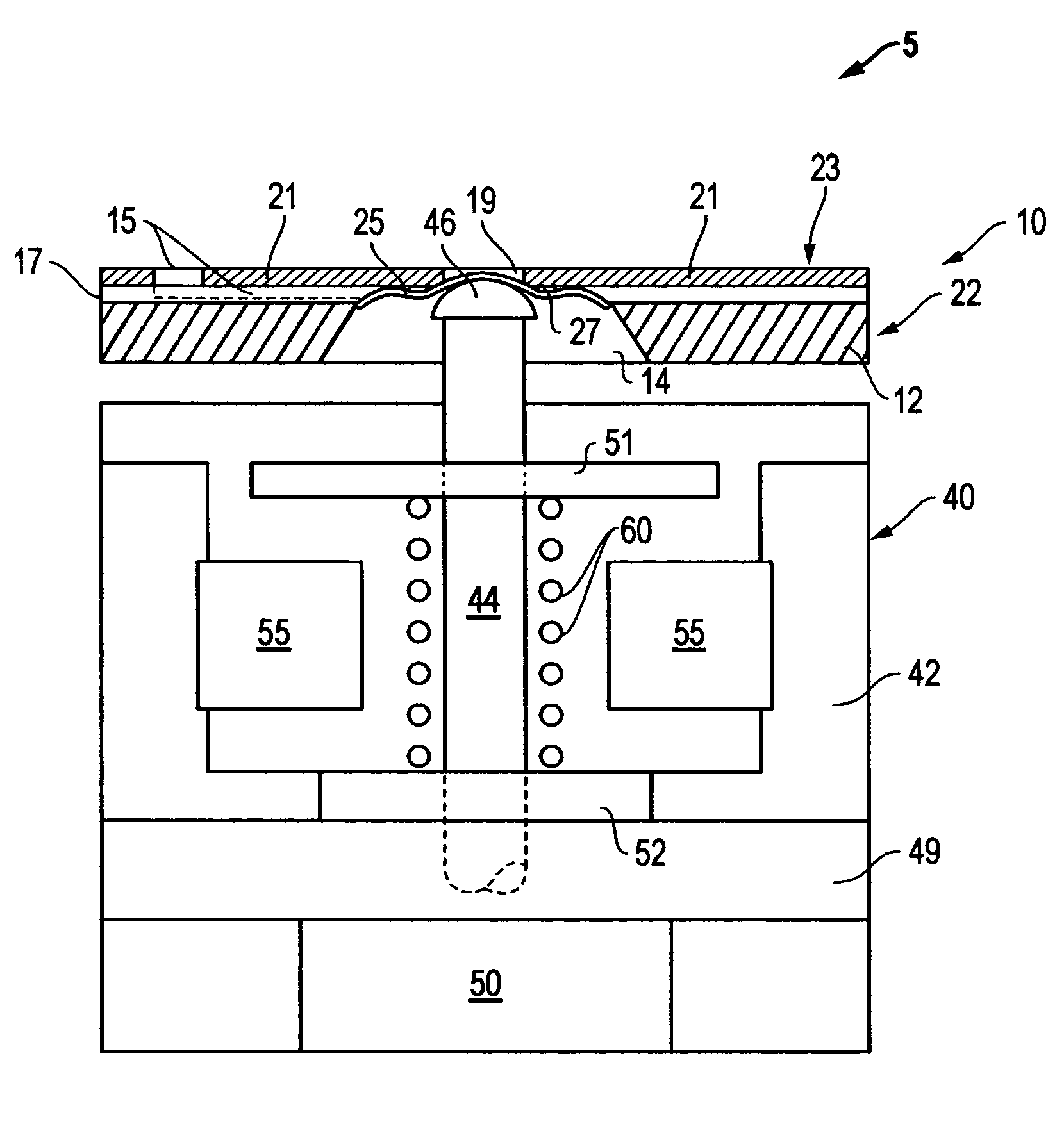
[0033]For a more complete understanding of the present invention, preferred embodiments of the present invention are illustrated in the Figures. Like numerals being used to refer to like and corresponding parts of the various accompanying drawings. It is to be understood that the disclosed embodiments are merely exemplary of the invention, which may be embodied in various forms.

[0034]FIG. 1 illustrates one aspect, among others, of apparatus 5 for selectively channeling a fluid. The apparatus 5 (which is also referred to herein as a valve) includes a fluid control assembly 10. In operation, the fluid control assembly 10 permits or prevents the flow of a high temperature fluid without chemically reacting with the high temperature fluid. Furthermore, in one exemplary embodiment, the apparatus 5 may be miniaturized to occupy a volume of less than one cubic centimeter and a mass of less than one gram to control the flow of a high temperature fluid without chemically reacting with the hig...


PUM


Abstract

An apparatus for selectively channeling a high temperature fluid without chemically reacting with the fluid. The apparatus includes an inlet and a membrane positioned adjacent to the inlet, each composed of a chemically inert material. The membrane is formed by compressive preloading techniques. The apparatus further includes a seat disposed on the inlet adjacent to the membrane. The seat is composed of a heat resistant and chemically inert material. Operation of the apparatus requires that the temperature of the fluid remains below the chemical characteristic melting point of the seat. The apparatus further includes an actuator coupled to the membrane for rendering the membrane in an open and a closed position with respect to the seat. Specifically, the actuator supplies a load in the normal direction to the membrane to selectively engage the membrane in a plurality of predetermined configurations. Operatively, the apparatus receives the fluid at the inlet. The fluid is received at a high temperature and is directed from the inlet to the membrane. In the closed position, the actuator engages the membrane to prevent the fluid from flowing from the inlet between the membrane and the seat. Alternatively, in the open position, the actuator engages the membrane to permit fluid flow from the inlet between the membrane and the seat to at least one outlet provided by the apparatus. In one exemplary embodiment, the fluid may be discharged from the at least one outlet to a sensor in fluid communication with the at least one outlet. Accordingly, the sensor may measure the fluid channeled through the heat resistant and chemically inert environment provided by the apparatus.

Description

STATEMENT OF GOVERNMENT INTEREST[0001]This invention was developed under contract no. DE-AC04-94AL8500 between Sandia Corporation and the United States Department of Energy. The United States Government reserves certain rights in this invention.BACKGROUND OF THE INVENTION[0002]1. Field of the Invention[0003]The present invention generally relates to an apparatus for selectively channeling a fluid. More particularly, but not by way of limitation, the present invention relates to a device and method for selectively channeling a fluid at a high temperature while providing a heat resistant and chemically inert flow path.[0004]2. Description of the Related Art[0005]Devices for controlling fluid flow are well known. For a wide variety of applications, the flow of either a gas or a liquid is often regulated by a valve. Illustratively, among other examples, valves may be applied for controlling the flow of a coolant fluid to an automobile radiator, controlling flow of intravenous fluids to ...

Claims


Application Information

Patent Timeline
Patent Type & Authority Patents(United States)
IPC IPC(8): F16K31/08
CPCF16K7/12F16K31/0672F16K99/0001F16K99/0015F16K99/0046F16K2099/0069F16K2099/0074
Inventor RIGHTLEY, MICHAEL JOSEPH
Owner NAT TECH & ENG SOLUTIONS OF SANDIA LLC
Why Eureka
Try Eureka