Burnishing head

a head and head technology, applied in the direction of maintaining the head carrier alignment, manufacturing tools, instruments, etc., can solve the problems of less compliance to surface abnormalities or particulates, fewer time for the head to recover, and the lack of such transducers in the head

Inactive Publication Date: 2008-01-01
WESTERN DIGITAL TECH INC +1
View PDF53 Cites 75 Cited by
  • Summary
  • Abstract
  • Description
  • Claims
  • Application Information

AI Technical Summary

Benefits of technology

[0016]A burnishing head in accordance with our invention comprises rails having outer side walls that are at an angle with respect to a central axis of the head. This is desirable for particle removal. Also, since the central axis of the slider is parallel to that of suspension, it takes less time for the head to recover when head-disk interaction occurs due to better flying characteristics.
[0019]We have discovered that increasing the height of the burnishing rails compared to prior art burnishing heads enhances performance. The rails typically have a height greater than 30 μm, and in one embodiment, between 50 and 100 μm. It is believed that the higher rail walls permit increased free space and air flow for displaced particles to be ejected from the head / disk interface without being reattached.
[0020]We have also discovered that providing rails with side walls close to vertical also enhances burnishing performance. In one embodiment, the side walls are at an angle greater than 75°, and in one embodiment between 80 and 90°. We believe that having steep rail side walls is superior because if the rail walls are not steep, the vertical component of the force applied by the burnishing head to the contaminant particles tends to drive the particles downward into the disk instead of sweeping the particles off of the disk surface. Also the steep side walls result in a stiffer air bearing due to increased air leakage and results in less compliance to surface abnormalities or particulates.

Problems solved by technology

Burnishing heads typically lack such transducers.
This is undesirable for burnishing operation because unstable flying of the head could result in head-disk interaction causing defect generation on the disk.
Also the steep side walls result in a stiffer air bearing due to increased air leakage and results in less compliance to surface abnormalities or particulates.

Method used


Image

  • Burnishing head
  • Burnishing head
  • Burnishing head

Examples


Embodiment Construction

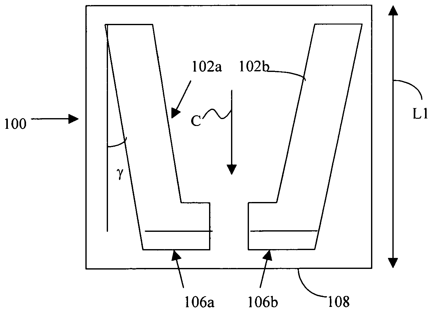
[0037]FIGS. 3A to 3C illustrate a burnishing head 100 constructed in accordance with our invention. Burnishing head 100 comprises rails 102a, 102b extending from a generally planar bottom surface 104 of head 100. Portions 106a, 106b of rails 102a, 102b, adjacent a leading edge 108 of head 100, are sloped at an angle β for aerodynamic reasons. In one embodiment, angle β is 18 minutes with respect to the rest of the air bearing surfaces 110a, 110b of rails 102a, 102b.

[0038]In one exemplary embodiment, rails 102 extend a height H2 between 50 and 100 μm from surface 104. Head 100 has a width W1 of 60 mils and a length L1 of 80 mils. Rails 102a, 102b extend a distance greater than half of length L1, and typically extend length L1 or a distance slightly less than length L1. Outer walls 112a, 112b of rails 102a, 102b form an angle γ of 15° with respect to a central axis C of head 100. These dimensions, however, are merely exemplary.

[0039]Burnishing head 100 may be made of any appropriatel...


PUM

PropertyMeasurementUnit
radiusaaaaaaaaaa
heightaaaaaaaaaa
anglesaaaaaaaaaa

Abstract

A burnishing head comprises at least two rails, each rail having an inner wall and an outer wall. The outer walls are at an angle relative to one another and relative to a central axis of the burnishing head. This angle permits the burnishing head to exhibit improved recovery time if it contacts a disk being burnished. The rail walls are vertical, and the corner between the rail walls and the top surface of the rails is sharp.

Description

[0001]This application claims priority based on our U.S. Provisional patent applications 60 / 773,190 (filed Feb. 13, 2006) and 60 / 773,266 (filed Feb. 14, 2006), incorporated herein by reference.BACKGROUND OF THE INVENTION[0002]This invention relates to burnishing heads for burnishing magnetic disks and methods for burnishing magnetic disks.[0003]Magnetic disks are typically manufactured with the following method:[0004]1. An aluminum alloy substrate is electroless plated with a nickel-phosphorus alloy.[0005]2. The plated substrate is textured.[0006]3. One or more underlayers, one or more magnetic layers, and one or more protective overcoats are deposited on the plated, textured substrate. (It is also known to deposit other layers onto the substrate as well.)[0007]4. A lubricant is applied to the protective overcoat.[0008]5. The resulting disk is then burnished.[0009]During burnishing, the disk is rotated, and a burnishing head flies over the disk to remove undesired contaminant partic...

Claims


Application Information

Patent Timeline
Patent Type & Authority Patents(United States)
IPC IPC(8): B24B1/00
CPCG11B5/3169G11B5/8404Y10T29/47
Inventor SINGH, BALVINDERTEMPLE, HOWARDPATEL, LEGAL REPRESENTATIVE, ROHINIPATEL, LEGAL REPRESENTATIVE, RAVIPETERS, LEGAL REPRESENTATIVE, GEERAPATEL, DECEASED, JAYADEV
Owner WESTERN DIGITAL TECH INC
Why Eureka
Try Eureka