Calibration method for an imaging device

a technology of imaging device and calibration method, which is applied in the field of image printing device, can solve the problems of inaccurate color reproduction, poor fit, inaccurate trcs, etc., and achieve the effect of reducing the adverse effects of streaks

Active Publication Date: 2008-01-01
XEROX CORP
View PDF23 Cites 13 Cited by
  • Summary
  • Abstract
  • Description
  • Claims
  • Application Information

AI Technical Summary

Benefits of technology

[0019]The above needs, as well as others, are fulfilled by providing a method and arrangement for creating a tone reproduction c

Problems solved by technology

A problem is that, due to manufacturing variations, different imaging devices can output different intensities of color based on identical image data.
However, from a cost viewpoint, it is desirable to minimize the number of test patches that are printed, since printing test patches consumes a significant amount of colorant.
One source of inaccuracies in TRCs is spatial variation of operation of the imaging device being calibrated.
In particular, even a single imaging device does not always deposit a same amount of marking agent for a given input color value at different spatial locations on the page.
As a result, subsequent calibration step

Method used


Image

  • Calibration method for an imaging device
  • Calibration method for an imaging device
  • Calibration method for an imaging device

Examples


Embodiment Construction

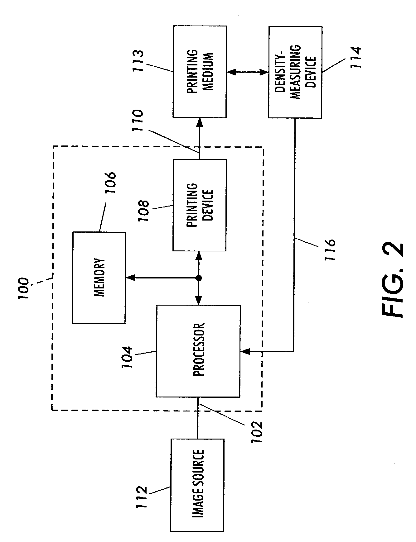
[0035]FIG. 2 shows a system that prints test patches, measures color output values of the test patches, and calibrates the color output characteristics of the system based upon the measured color output values. The system includes an arrangement 100 according to embodiments of the present subject invention, an image source 112, a print medium 113, and a color-measuring device 114.

[0036]The arrangement 100 includes an input 102, a processor 104, a memory 106, a printing device 108, and an output 110. In general, the arrangement receives at the input 102 an image and generates at the output 110 printed pages of recording media from which the image may be physically reconstructed.

[0037]The image source 112 can be any suitable device that generates image data corresponding to a two-dimensional image. The image source 112 is further configured to provide image data corresponding to an array of rows and columns of test patches that are used to calibrate the arrangement 100, as will be dis...


PUM


Abstract

A method includes forming a plurality of test patches in an array of orthogonal rows. The test patches are formed by using at least one printhead in an imaging machine. Each of the test patches is associated with a respective one of a plurality of initial input color values. The array of test patches includes a plurality of rows of varied-input test patches and at least one row of first equivalent-input test patches. A respective output color value of each of the test patches is measured. At least one first mathematical relationship is generated based on the output color values of the at least one row of first equivalent-input test patches. A plurality of adjusted input color values are calculated for respective ones of the varied-input test patches. Each adjusted input color value is calculated based upon the generated at least one first mathematical relationship. A second mathematical relationship is computed between the adjusted input color values and the output color values. The imaging machine is calibrated by using the second mathematical relationship.

Description

FIELD OF THE INVENTION[0001]The subject invention relates generally to an image printing device, and in particular, an improved method of creating a tone reproduction curve for an image printing device.BACKGROUND OF THE INVENTION[0002]An imaging device in the form of a printer or copier typically creates images using combinations of four colors of marking agents or colorants, such as cyan, magenta, yellow and black (CMYK). The images are created based on image data which assigns at least one of the four colors and a numerical color intensity or input color value to each picture element or pixel in the image.[0003]A problem is that, due to manufacturing variations, different imaging devices can output different intensities of color based on identical image data. The density of the toner laid down on the print medium determines the color intensity. The denser or thicker the toner is laid down on a white print medium such as paper, the less white is visible through the toner on the pap...

Claims


Application Information

Patent Timeline
IPC IPC(8): G06F15/00G06K9/40H04N1/46H04N1/58H04N1/60
CPCH04N1/6033
Inventor KLASSEN, R. VICTORBALA, RAJA
Owner XEROX CORP
Why Eureka
Try Eureka