Mammograph system with a face shield

a technology of mammograph system and face shield, which is applied in the direction of x-ray tube, application, diagnostics, etc., can solve the problems of increasing the risk of shield loss, face shield material fatigue, damage, etc., and achieves no or less material fatigue or even damage, easy adjustment, and enhanced variability

Active Publication Date: 2008-01-01
SIEMENS HEALTHCARE GMBH
View PDF3 Cites 113 Cited by
  • Summary
  • Abstract
  • Description
  • Claims
  • Application Information

AI Technical Summary

Benefits of technology

[0009]In one exemplary embodiment, a mammograph system includes an X-ray emitter head. A face shield is supported movably in the X-ray emitter head and is movable at least into a position of repose and into a protection position. When in the repose position, the face shield is retracted into the X-ray emitter head. When in a protection position, at least a portion of the face shield protrudes from the X-ray emitter head. When in the protection position, the face shield prevents a patient's body, more specifically, a patient's head, from unintentionally entering the region below the X-ray emitter head in the mammograph system.
[0010]The face shield, which is supported by the X-ray emitter head, makes additional storage provisions unnecessary. In the repose position, the face shield is retracted into the X-ray emitter head and is removed from the entire working area and from the surroundings of the mammograph system. Because the face shield is supported in the X-ray emitter head, it is unnecessary to install or remove the face shield, possibly resulting in no or less material fatigue or even damage. When a patient is positioned at the mammograph system, the face shield can be moved outward or retracted, something that is difficult to do in conventional systems.
[0011]In one exemplary embodiment, the face shield can be locked in a predetermined first protection position. The term locking is broadly defined as a manual lock or an automatic lock. For example, the face shield may be locked by a detent position. A first predetermined protection position may be set, and thus the face shield can be easily adjusted without close attention on the part of the equipment operator.
[0012]In another exemplary embodiment, the face shield can be locked in a second predetermined protection position. As a result, a second protection position can easily be assumed, which enhances the variability.

Problems solved by technology

This makes storing the face shields more complicated and increases the risk that a shield will be lost.
There is also the danger that the face shield will suffer material fatigue and be damaged from being frequently installed and removed from the mammograph system.
Because the face shield is supported in the X-ray emitter head, it is unnecessary to install or remove the face shield, possibly resulting in no or less material fatigue or even damage.
When a patient is positioned at the mammograph system, the face shield can be moved outward or retracted, something that is difficult to do in conventional systems.
Dirt can damage the vulnerable filter by dropping through the X-ray beam opening.

Method used


Image

  • Mammograph system with a face shield
  • Mammograph system with a face shield

Examples


Embodiment Construction

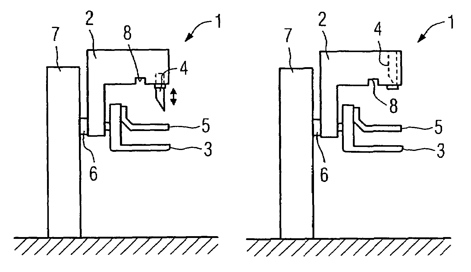
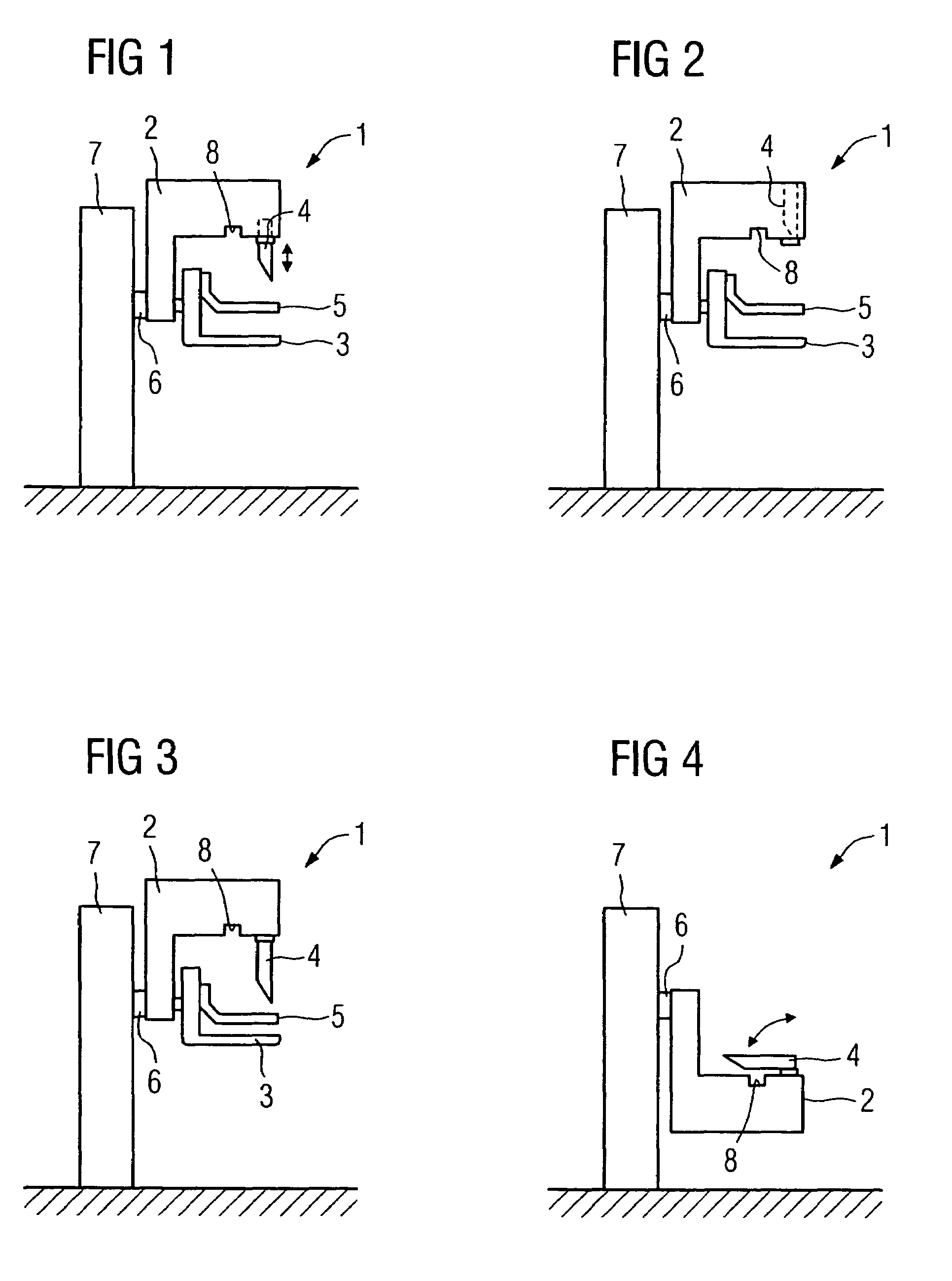
[0020]According to one exemplary embodiment, a mammograph system 1 includes a floor stand 7 that supports an X-ray emitter head 2. The X-ray emitter head 2 is supported by a receptacle 6 that is rotatable about a horizontal axis. An object table 3 is supported rotatably by the X-ray emitter head 2. A patient's breast to be examined is placed on the object table. In conjunction with the object table 3, a compression plate 5 serves to fix and / or compress the breast on the object table 3.

[0021]The X-ray emitter head 2 includes an X-ray source, a shutter element, and a filter or filters (not shown). The X-ray source generates an X-ray. The X-ray, after passing through the shutter element and the filter or filters, leaves the X-ray emitter head 2 through the X-ray beam opening 8. After passing through the breast to be examined the X-ray strikes the object table 3. The compression plate 5 located between the X-ray beam opening 8 and the object table 3 is made from a radio transparent mate...


PUM


Abstract

The present embodiments relate to a mammograph system with a face shield. The mammography system includes an X-ray emitter head; an object table; and a face shield. The face shield is movably supported by the X-ray emitter head and is movable into at least first and second positions. In the first position, the face shield is retracted into the X-ray emitter head. In the second position, at least a portion of the face shield protrudes out of the X-ray emitter head.

Description

[0001]The present patent document claims the benefit of the filing date of DE 20 2005 013 910.6, filed Sep. 2, 2005.BACKGROUND[0002]1. Field[0003]The present embodiments relate to a mammograph system with a face shield.[0004]2. Related Art[0005]Mammograph systems with a face shield have been previously used. Typically, a mammograph system includes an object table and an X-ray emitter head. A breast to be examined is positioned on the object table. The X-ray emitter head accommodates at least one X-ray source. The X-ray emitter head is typically pivotable and is generally positioned above the object table. The X-ray emitter head makes an X-ray image of the breast to be examined. The X-ray detector is located in or below the object table. A patient to be examined typically stands in front of the mammograph system.[0006]During the operation of a mammogram, a patient approaches close to the mammograph system. The patient's breast is then fixed on the object table and compressed by a com...

Claims


Application Information

Patent Timeline
Patent Type & Authority Patents(United States)
IPC IPC(8): A61B6/04A61B6/00A61B6/10
CPCA61B6/107A61B6/502
Inventor RAMSAUER, MARTIN
Owner SIEMENS HEALTHCARE GMBH
Why Eureka
Try Eureka