Device and method for interconnecting framing components

a technology of framing components and devices, applied in the direction of building reinforcements, construction, building roofs, etc., can solve the problems of creating a whole new set of problems, unable to solve simple strap problems, and difficult to carry, store, and stack

Inactive Publication Date: 2008-01-08
SACKETT GERALD L
View PDF13 Cites 38 Cited by
  • Summary
  • Abstract
  • Description
  • Claims
  • Application Information

AI Technical Summary

Benefits of technology

[0016]The present invention is a framing component interconnecting device for simultaneously anchoring, orienting, bracing, and interconnecting framing components. It is particularly useful for interconnecting a spanning member and its supporting components. Among the many objectives met by the invention are 1) maintaining the long axis of the spanning member at a fixed and proper angle to the long axis of the supporting component; 2) preventing the two framing components from sliding to-and-fro with respect to each other during assembly of the frame, 3) providing a connection between the two components that is sufficiently strong to withstand uplift and shear forces, 4) holding the spanning member vertically, plumb, and on edge with respect to the upper surface of its supporting component, and 5) maintaining the proper bearing point of the spanning member on the supporting component.
[0020]My invention has a number of features that facilitate proper alignment of the two framing components. First, the device is pre-attached to the spanning member at the bearing point of the spanning member such that an edge of the device will serve as a sight-line to indicate when the bearing point is properly aligned on the supporting component. This allows the spanning member to be quickly positioned correctly lengthwise with respect to the supporting component. Second, when the components are in proper position one to the other, the anchor strap hinge also acts as a sight-line because it is juxtaposed with the upper edge of the vertical surface of the supporting component. When the anchor strap is bent downwards about its hinge and flush against the supporting component, the two components are necessarily brought into proper alignment. Third, when the anchor strap is deployed and lies flush against the vertical surface of the supporting component, the builder knows that the two framing components are square. Fourth, the connecting plates hold the spanning member plumb and vertical with respect to the upper surface of the supporting component. Fifth, the connecting flaps, when deployed and nailed to the supporting component, prevent rotation and sliding of the spanning member relative to the supporting component.

Problems solved by technology

While the foregoing examples of tie-down devices are reasonably effective in resolving the problems of uplift and shear forces, these simple straps do not resolve problems related to properly orienting and squaring framing components relative to one another.
While such devices are effective in securing spanning members to support components and in facilitating the squaring of the interconnected framing components, the complex shapes of these devices create a whole new set of problems.
For instance, they are difficult to handle, carry, store, and stack.
Also, such devices cannot reasonably be pre-installed on framing components without making the components both difficult and dangerous to handle due to the sharp sheet metal flaps and tabs extending in multiple directions.
Because such devices cannot be pre-installed they must be carried to the work site, stored there until needed, and then carried to the point at which they are used.
This results in wasted materials and time as the loose pieces are dropped, misplaced, kicked around, and damaged.

Method used


Image

  • Device and method for interconnecting framing components
  • Device and method for interconnecting framing components
  • Device and method for interconnecting framing components

Examples


Embodiment Construction

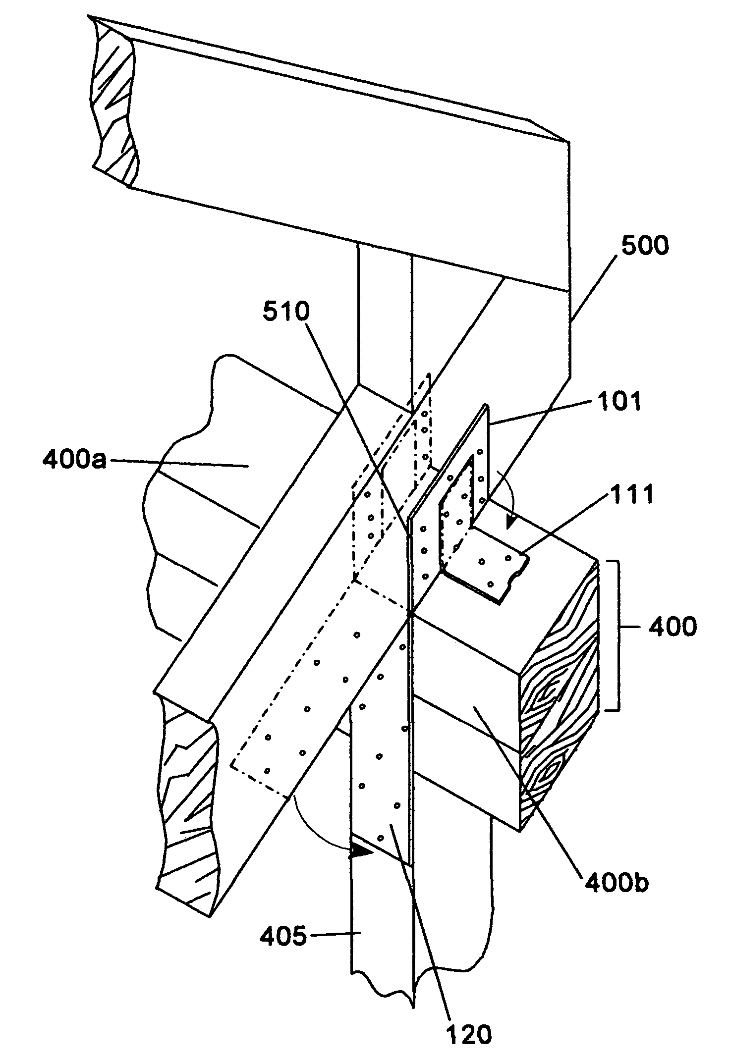
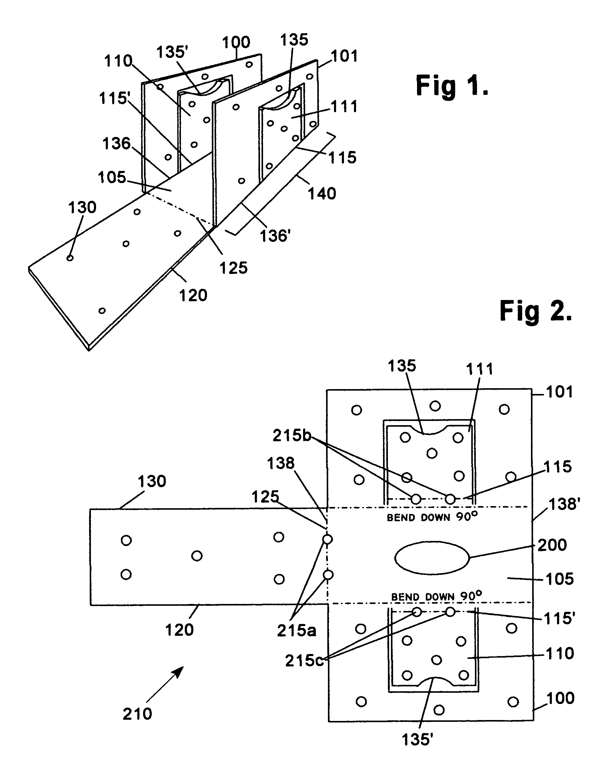
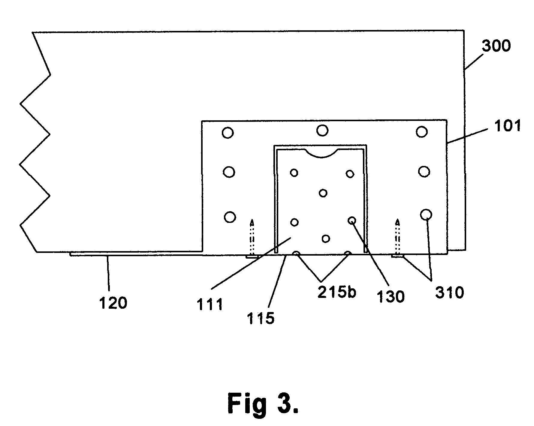
[0030]The inventive concepts and novel features of my invention are described herein with reference to specific embodiments, which embodiments represent the best mode known to me for making and using my invention. However, it is to be noted that the embodiments as described herein are not meant to limit the scope of my invention but rather are representative of many possible embodiments that incorporate the inventive concepts of my invention.

1. STRUCTURAL FEATURES

[0031]In the preferred embodiment, the invention is fabricated from sheet metal that is sufficiently thick to meet the necessary strength requirements and yet sufficiently flexible to allow the various flaps and straps to be deployed as described below. Sheet metal of about 18 to 22 gauge is appropriate for most applications. Of course, the invention may be made of any material or combination of materials having the requisite strength and flexibility characteristics.

[0032]The invention exists in two configurations: a non-de...


PUM


Abstract

The present invention is a framing component interconnecting device that is particularly useful for interconnecting a spanning member and its supporting components. While the device may be used in a number of ways to facilitate frame construction, the preferred mode of use is to pre-attach it at the bearing points of a spanning member during pre-assembly of the spanning member. Because the device is not obtrusive while it is in what is referred to herein as a “non-deployed configuration,” the device thus attached to a spanning member does not hinder or complicate storing, transporting, and handling the spanning member. The device incorporates an anchor strap and connecting flaps that can be deployed in order to interconnect the spanning member to its supporting component once the spanning member has been raised into position. In its deployed configuration, the device anchors, orients, braces, and interconnects one framing component to another.

Description

BACKGROUND OF THE INVENTION[0001]1. Field of the Invention[0002]My invention relates to devices for facilitating the construction on of frame buildings and other frame structures, and more specifically, my invention relates to devices for simultaneously anchoring, orienting, bracing and interconnecting framing components, particularly spanning members and supporting components.[0003]2. Problems Solved by the Invention[0004]Frame-based buildings are normally constructed by initially assembling a frame from a plurality of elemental framing components. The elemental framing components are typically elongated pieces of wood or metal having a rectangular or square cross-section. Of particular interest with respect to the present invention are spanning members, which are defined herein as framing components that span a space and are supported by two or more supporting components. Generally, as in rafters, trusses, and floor joists, spanning members are oriented horizontally and are suppor...

Claims


Application Information

Patent Timeline
Patent Type & Authority Patents(United States)
IPC IPC(8): E04B7/04E04B1/38E04C5/00
CPCE04B7/045E04B1/2608
Inventor SACKETT, GERALD L.
Owner SACKETT GERALD L
Why Eureka
Try Eureka