Method of determining the sound pressure resulting from a surface element of a sound emitting device

a surface element and sound pressure technology, applied in seismology, geological measurements, weighing apparatuses, etc., can solve the problems of complex identification of noise sources and transmission paths, noise can seriously jeopardize the comfort of people, mechanical structures, and noise can seriously jeopardize the health of people, so as to avoid rigid surface elements

Active Publication Date: 2008-01-08
BRUEL & KJAER SOUND & VIBRATION MEASUREMENT
View PDF9 Cites 6 Cited by
  • Summary
  • Abstract
  • Description
  • Claims
  • Application Information

AI Technical Summary

Benefits of technology

[0021]A more general method uses also the “operational” sound pressure and the particle velocity created by the volume velocity sound source, whereby the requirement for rigid surface elements is avoided.

Problems solved by technology

In complex structures with several noise sources, such as mentioned above, it can be complicated to identify noise sources and transmission paths and their contributions to the perceived noise.
Noise can seriously jeopardize not only comfort but also the health of humans.
Mechanical structures such as body and wall panels can vibrate and emit noise, and large structures can have “hot spots” that emit more noise than “cold spots”.

Method used


Image

  • Method of determining the sound pressure resulting from a surface element of a sound emitting device
  • Method of determining the sound pressure resulting from a surface element of a sound emitting device
  • Method of determining the sound pressure resulting from a surface element of a sound emitting device

Examples


Embodiment Construction

[0025]The measurement set-up used in the invention is as follows.

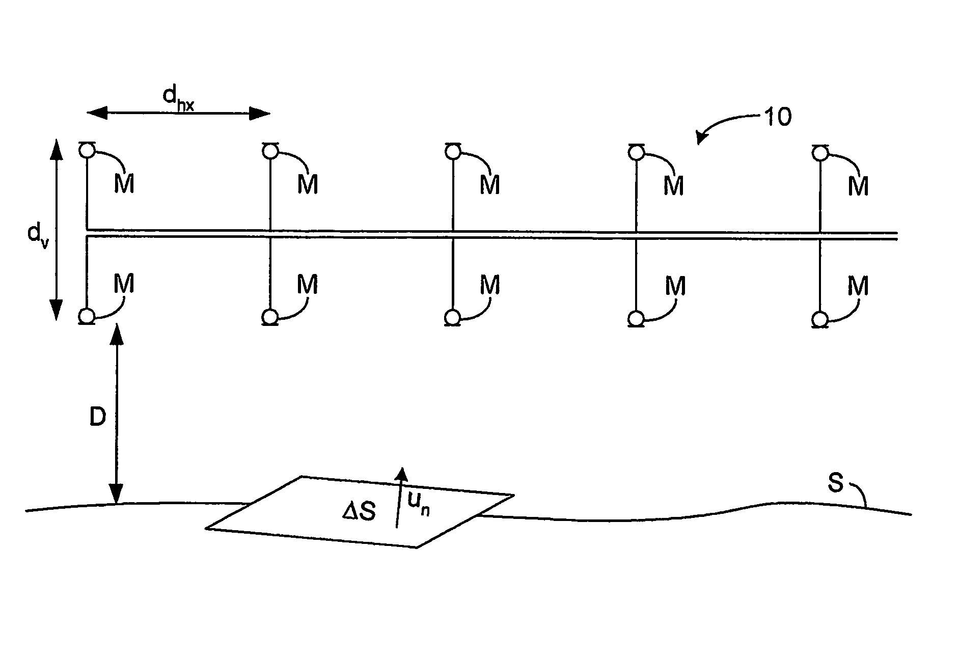
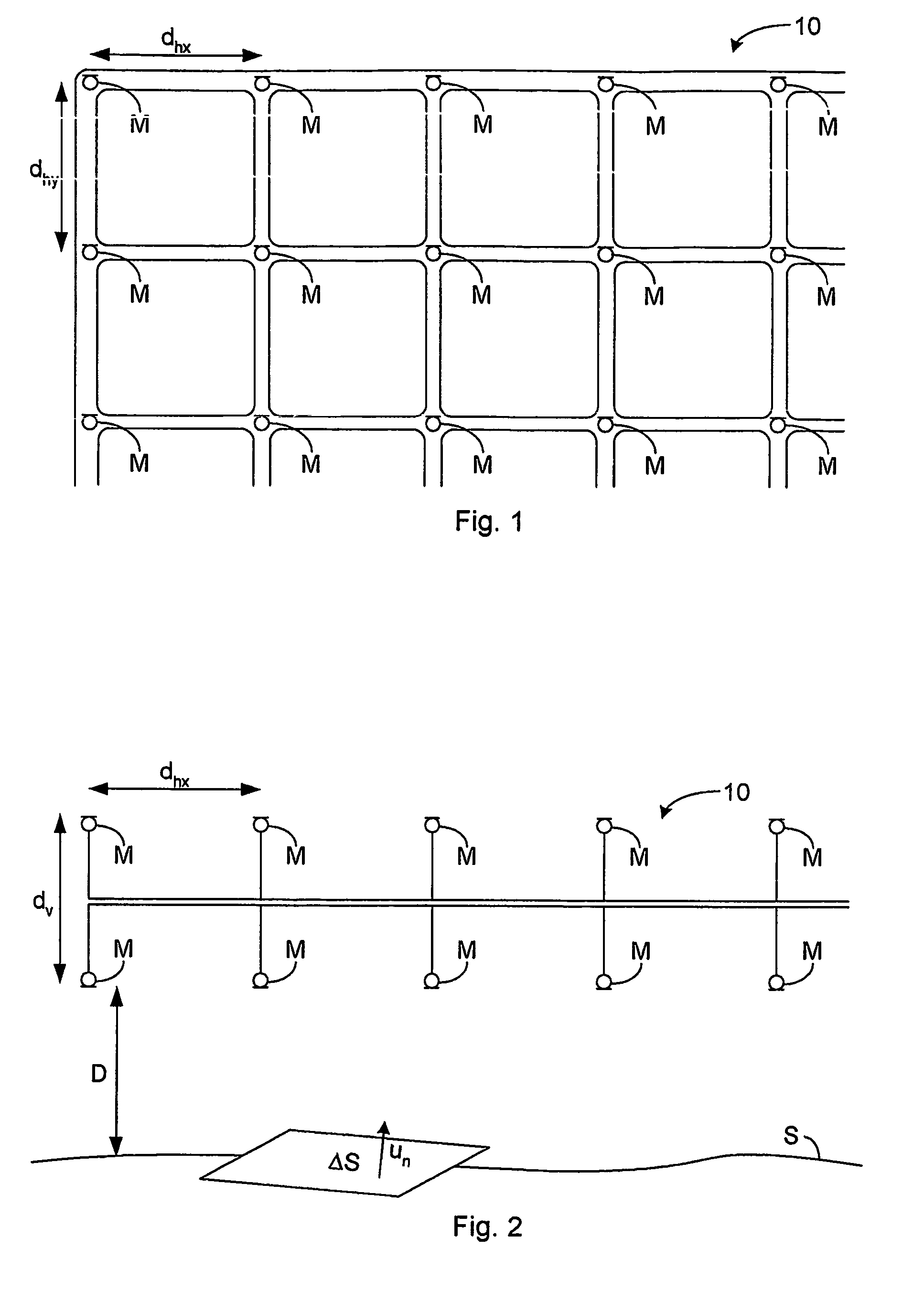
[0026]In FIGS. 1 and 2 a three-dimensional array 10 of a plurality of microphones M is shown. The term “microphone” is here used as the generally accepted term for a transducer that generates an (electrical) output signal in response to pressure variations in the fluid (air, water etc.) that surrounds the transducer. The array comprises two identical, parallel layers of microphones M spaced a vertical distance dv apart. In each layer the microphones are distributed in two sets of parallel rows forming a square grid with the rows spaced horizontal distances dhx and dhy, respectively, apart. In the preferred embodiment shown, the vertical distance dv and the horizontal distances dhx and dhy are identical, whereby the microphones are uniformly distributed and form a cubic lattice. A non-periodic or non-uniform, such as pseudo-random, distribution of the microphones can also be used. The microphones have well-defined, pref...


PUM


Abstract

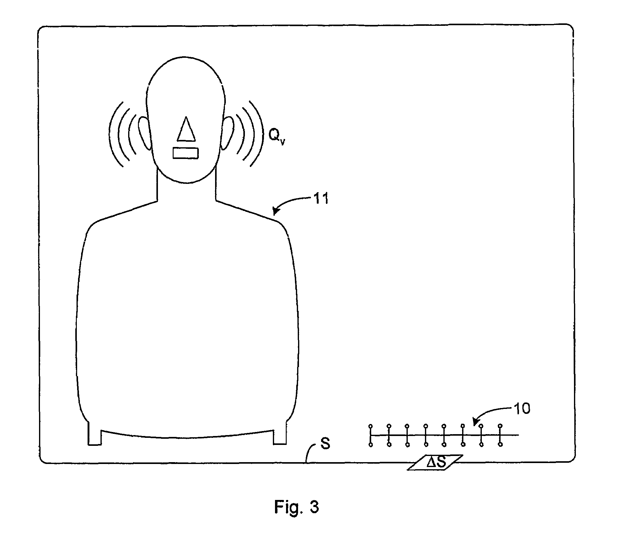
A three-dimensional array (10) of microphones (M) is used to determine the three-dimensional sound field above a surface element (ΔS) of a sound emitting surface (S), and the air-particle velocity (un) at the surface element (ΔS) is determined using Near-Field Acoustical Holography (NAH). A volume velocity sound source (11) is used to emit a volume velocity (Qv) in a listening position, and the array (10) of microphones (M) is used to determine the resulting three-dimensional sound field above the surface element (ΔS), and using NAH the resulting sound pressure at the surface element (ΔS) is determined. The acoustic transfer function (H) between the surface element (ΔS) and the listening position is assumed to be reciprocal and is determined as the ratio of the resulting sound pressure at the surface element (ΔS) to the volume velocity (Qv). The sound pressure in the listening position resulting from the surface element (ΔS) is determined as Δp=H.(un. ΔS).

Description

FIELD OF THE INVENTION[0001]The invention relates to the detection and identification of sound sources, and noise sources in particular, with the purpose of reducing noise emission.BACKGROUND OF THE INVENTION[0002]Protection of the environment and human beings has become increasingly important. Buildings, vehicles such as cars, buses and aircraft, household appliances and industrial machinery have noise producing components such as engines, motors, gears, transmissions etc. In order to protect individuals from such noise, the noise generating components and the transmission path of the noise to a human being have been investigated with the purpose of reducing the generated noise at the source and of reducing the noise transmitted from the source to human beings.[0003]Testing of acoustic properties of noise generating and noise transmitting media such as mechanical structures and air or other fluids is an important part of the process of noise reduction. In complex structures with se...

Claims


Application Information

Patent Timeline
Patent Type & Authority Patents(United States)
IPC IPC(8): G01H3/12G01H3/10
CPCG01H3/10
Inventor HALD, JORGEN
Owner BRUEL & KJAER SOUND & VIBRATION MEASUREMENT
Why Eureka
Try Eureka