Dual temperature indicator stick holder

a technology of temperature indicators and stick holders, which is applied in the field of temperature indicators, can solve the problems of insufficient holders of temperature indicators, inability to fix temperature indicators, and inability to meet the current state of the art of temperature indicators, and achieve the effect of easy replacement of indicator sticks

Inactive Publication Date: 2008-01-08
LA CO IND INC
View PDF26 Cites 14 Cited by
  • Summary
  • Abstract
  • Description
  • Claims
  • Application Information

AI Technical Summary

Benefits of technology

[0011]In accordance with one aspect of the present invention, a dual temperature indicator stick is disclosed having a first indicator stick positioned along a first axis and comprised of a compound which melts at a first given temperature. The dual temperature indicator stick also includes a second indicator stick positioned along a second axis and comprised of a compound which melts at a second given temperature, and a connector. The connector physically connects the first and second indicator sticks together in a side-by-side relationship along different axes and allows for easy replacement of the indicator sticks.

Problems solved by technology

Problems exist with the current state of the art of temperature indicators.
Existing holders for temperature indicators are not satisfactory.
Such holders are often limited in their ability to fix the temperature indicator stick in position.
Operator use of the temperature indicator stick results in pressure exerted on the end of the stick during marking which causes the stick to retract into the housing.
Another problem is that current temperature indicators are configured to hold one temperature indicator stick, limiting temperature detection to a single temperature value.
Operators desiring to detect several temperatures must carry or locate multiple temperature indicators, which is often tedious.
Furthermore, since current temperature indicators are configured for a single stick, the indicator sticks are generally positioned within tubular-shaped housings that are difficult to adjust during use, especially in welding and other heat-treating processes that require an operator to wear gloves and other heat-protection equipment which limits the operator's ability to manipulate small objects.
It is difficult for an operator to hold a welding gun in one hand, for example, and two temperature indicator sticks in the other hand while wearing heat-resistant gloves.

Method used


Image

  • Dual temperature indicator stick holder
  • Dual temperature indicator stick holder
  • Dual temperature indicator stick holder

Examples


Embodiment Construction

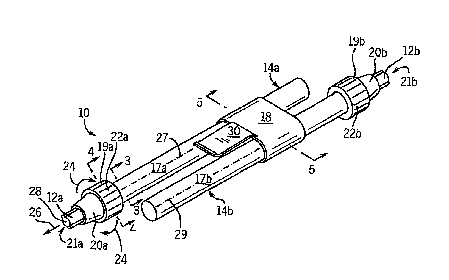
[0024]Various temperature detection monitors are used by the welding, metal fabrication and heat treatment industries to measure temperatures of materials. Determining surface temperatures is critical during welding and metal fabrication processes, such as pre-heat and post-weld heat treatment. Temperature monitoring is also important for determining operating temperatures of various mechanical, electrical, and hydraulic systems and components. These components, such as a motor or transformer, can be destroyed or alternatively have their device characteristics substantially altered if the components are not manufactured within a specified temperature range.

[0025]Several detection devices and methods exist to determine surface and operating temperatures. Some devices use gauges or electronic components having thermistors, whereas others use chemical compounds formed as temperature indicator sticks that feed through mechanical temperature indicators. Although each of these detection d...


PUM

PropertyMeasurementUnit
temperatureaaaaaaaaaa
resistanceaaaaaaaaaa
Temperatureaaaaaaaaaa

Abstract

An apparatus to combine temperature indicator sticks used in the welding, metal fabrication, and heat treatment industries and capable of identifying at least two given temperatures is disclosed. The apparatus includes a first temperature indicator stick aligned along a first axis and comprised of a compound which melts at a first temperature, and a second temperature indicator stick aligned along a second axis and formed of another compound which melts at a second temperature. The apparatus also includes a connector physically connecting and aligning the first and second indicator sticks.

Description

CROSS REFERENCE TO RELATED APPLICATIONS[0001]This application claims the benefit of prior U.S. patent application Ser. No. 09 / 682,843 filed Oct. 23, 2001 now U.S. Pat. No. 6,857,777 and entitled “DUAL TEMPERATURE INDICATOR STICK HOLDER.”BACKGROUND OF INVENTION[0002]The present invention relates generally to temperature indicators, and more particularly, to an apparatus and method to independently extend and retract a pair of temperature indictor sticks longitudinally aligned along two axes.[0003]Temperature indicators are well known in the welding, metal fabrication, and heat treatment industries. Such products are capable of determining surface temperatures during welding and metal fabrication processes. The products have also found use in heat-treatment processes, and can determine operating temperatures of mechanical, hydraulic, and electrical systems and components, such as transformers and motors.[0004]Initially, temperature sensing was conducted by sprinkling a few granules of...

Claims


Application Information

Patent Timeline
Patent Type & Authority Patents(United States)
IPC IPC(8): G01K1/00G01K11/00G01K11/06
CPCG01K11/06
Inventor DEONARINE, VICTOR
Owner LA CO IND INC
Why Eureka
Try Eureka