
Three-piece molding manifold

a three-piece molding and manifold technology, applied in the field of molding manifolds, can solve the problems of insufficient tack-welding, insufficient heat dissipation, and insufficient heat dissipation, and achieve the effect of reducing or eliminating the leakage of molten materials

Inactive Publication Date: 2008-01-08
NAT RES COUNCIL OF CANADA
View PDF10 Cites 1 Cited by
  • Summary
  • Abstract
  • Description
  • Claims
  • Application Information

AI Technical Summary

Benefits of technology

The patent describes a molding manifold that is used to distribute molten material in a molding process. The manifold has multiple components including inlet and outlet ports, flow channels, and a cover piece. The cover piece covers the flow channels to prevent leakage of the material. The cover piece is secured to the first half of the manifold and forms a hermetic seal with it. The heater grooves in the first half of the manifold are designed to efficiently heat the flow channels. The size and shape of the cover piece are designed to ensure a good seal and prevent interference with the flow channels. The second half of the manifold is securable to the first half and has complementary heater grooves to the first half. The cover piece is received in a cavity of the second half and is secured to it using welding, bolts, clamps, adhesives, or a combination of these methods. The invention provides a more efficient and effective molding manifold for use in molding processes.

Problems solved by technology

This design is complex requiring an inordinate amount of machining to produce the filling ducts / recesses and air ducts leading to heating element channels, and the brazing ducts leading to one matching surface.
Further, considerable amount of work is require to tack-weld individual filling tubes in a recess over each filling duct, fill braze powder into the ducts / tubes, and machine out filling tubes after furnace brazing.
Furthermore, expensive vacuum furnace equipment is require to braze the heating elements and braze the two halves of the manifold into an integrated unit.
Still further, brazing requires heating the entire manifold to about 1925° F., which deteriorates the mechanical properties of the manifold material and may cause deformation of the entire manifold.
Yet further, the entire procedure to produce the integrated manifold requires a longer production cycle.
Finally, furnace brazing may induce excess brazing material to leak into the flow channel, which will require expensive polishing procedures to clean.
Manufacturing of the individual duct and interlock elements is very labor intensive.
Manufacturing interconnected channel pipes is complex and expensive.
While reducing the risk of plastic leaking into the heater element channels, these designs are costly to manufacture, undesirably large and / or inefficient at heating the flow channels.
While reducing the risk of plastic leaking into the heater element channels, this design is costly to manufacture and inefficient at heating the flow channels.
Such a sealing method is not efficient and prone to failure.
Furthermore, this design permits resin to pool in the recession and permits resin pooled in the recession to bleed back into the hot runner channel contaminating subsequent shots of resin.
Thus, this design limits the ability to change resin type or color without disassembling the entire manifold.

Method used


Image

  • Three-piece molding manifold
  • Three-piece molding manifold
  • Three-piece molding manifold

Examples


Embodiment Construction

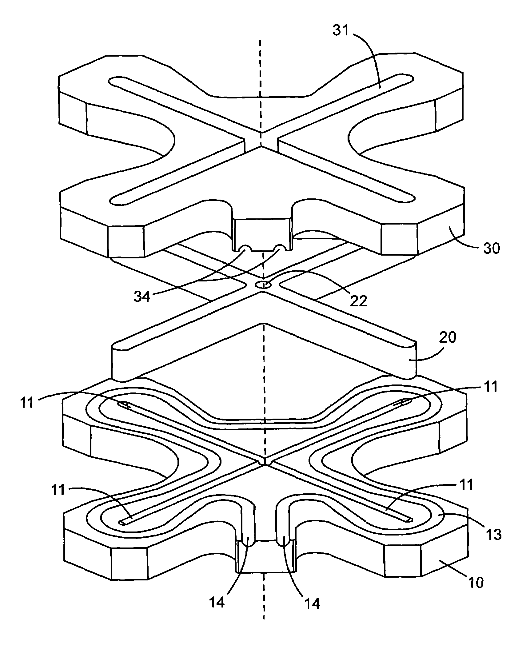
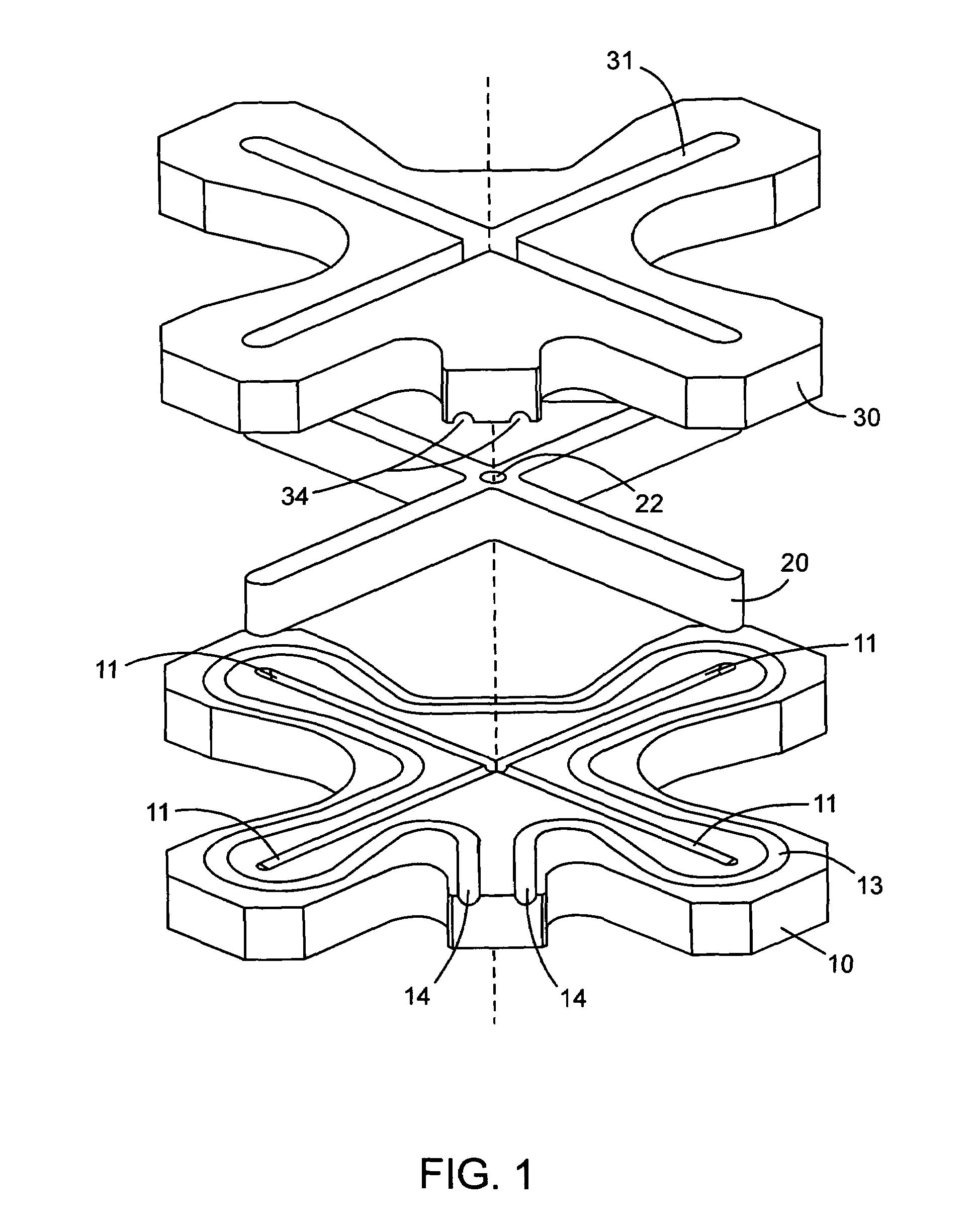
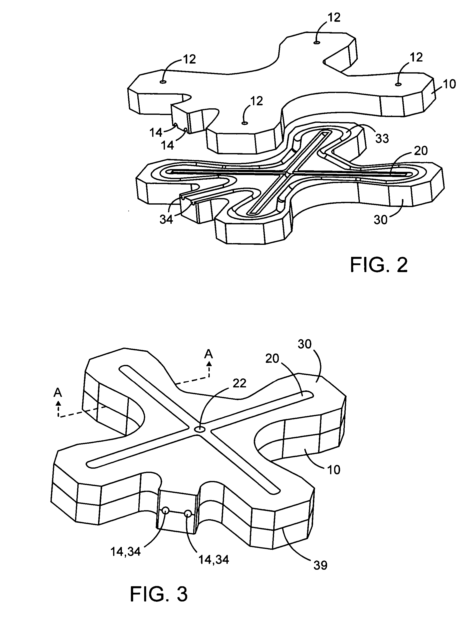
[0044]Referring to FIGS. 1-7, a three-piece 4-port manifold comprises first half 10, cover piece 20 and second half 30. First half 10 comprises flow grooves 11 radiating from a central point and terminating in outlet ports 12. Outlet ports 12 are perpendicular to flow grooves 11 and open out to the bottom of first half 10. First half 10 also has heater groove 13 for receiving an electrical heating coil (not shown). Heater groove 13 terminates at openings 14 through which the terminals of the heater coil may protrude out the side of first half 10.

[0045]Cover piece 20 comprises flow grooves 21 complementary to flow grooves 11 on first half 10. When assembled as shown in FIG. 3, flow grooves 11 match up with flow grooves 21 as illustrated in FIG. 7 to form flow channels through which molten plastic may flow. Cover piece 20 comprises central inlet port 22 for receiving molten plastic perpendicular to flow grooves 21. Cover piece 20 is just large enough to accommodate flow grooves 21 and...


PUM

PropertyMeasurementUnit
widthaaaaaaaaaa
pressureaaaaaaaaaa
shapeaaaaaaaaaa

Abstract

A hot runner molding manifold has a first half having flow grooves, a cover piece having flow grooves complementary to the flow grooves of the first half, and a second half securable to the first half and having a cavity for receiving the cover piece. The flow grooves of the first half and the cover piece form flow channels for distributing molten material from an inlet port to outlet ports. The cover piece is engaged with the first half, for example by welding, to reduce leakage of molten material out of the flow channels. Heater grooves in the first half, second half or both the first and second halves receive one or more heating elements for heating the flow channels.

Description

FIELD OF THE INVENTION[0001]The present invention relates to molding manifolds, particularly to hot runner manifolds for distributing molten materials to mold cavities.BACKGROUND OF THE INVENTION[0002]Multi-cavity molding, in particular for injection molding, is widely used for manufacturing multiple parts in a single mold during each cycle. Manifolds are required to direct molten material, e.g. plastics and metals, to a number of outlet ports through flow channels so that the molten material can be directed to multiple cavities to form parts. Hot runner manifolds use electric heating elements to keep the temperature of flow channels at the melting temperature of the molten material. During a production run, the heated material remains molten in the flow channels between shots, hence reducing material waste in the runner system and reducing the amount of finishing work required for the final parts.[0003]Hot runner manifolds are widely used and may be the only economic way to manufac...

Claims


Application Information

Patent Timeline
Patent Type & Authority Patents(United States)
IPC IPC(8): B29C45/00
CPCB29C45/2725B29C45/2738
Inventor XUE, LIJUECAMPBELL, GLEN ROBERTGOMES, MANUEL J.
Owner NAT RES COUNCIL OF CANADA
Learn More