Arrow with light emitting function, nock with light emitting function, and light emission control device to be used in arrow technical field

a technology of light emission control and arrow, which is applied in the direction of solid balls, hollow non-inflatable balls, sports apparatus, etc., can solve the problems of inability to confirm the origin of the arrow by light emission after, and the inability to maintain stable accuracy, so as to facilitate the confirmation of the locus of the arrow, the effect of eliminating erroneous operations and functional deterioration due to wear according to the frequency of us

Inactive Publication Date: 2008-01-08
TAKAHASHI YASUHIRO
View PDF12 Cites 40 Cited by
  • Summary
  • Abstract
  • Description
  • Claims
  • Application Information

AI Technical Summary

Benefits of technology

[0026]According to the arrow, the nock and the light emission control device of the invention described above, the electrical circuit is energized by an acceleration applied when a shooter discharges an arrow and the LED element emits light, and even after the arrow hits a target or the ground, etc., light is emitted for several seconds due to discharge from the capacitor, whereby it becomes possible to easily confirm the locus of the arrow and the position the arrow hit even in a dark playing field or a training field.
[0027]In addition, the electrical switch is not operated by mechanical operations, but is operated by using the acceleration applied to the arrow, so that erroneous operations and functional deterioration due to wearing according to the frequency of use are eliminated.
[0028]Furthermore, the electronic circuit includes an LED element, a transistor, and a capacitor, and is energized only while an acceleration is applied to the arrow, so that power consumption is very small and very economical.

Problems solved by technology

However, the light emitting means of the nock conducts electricity by separating the operating part 112 from the switch opening and closing pieces 108 by inertia of the switch operator 109 itself when the arrow 101 hits and stops, and makes the light emitting diode 106 emit light, so that the parts are worn out according to the number of times of use of the arrow and this changes the period of light emission and causes the switch part to be broken, and therefore there is a problem that stable accuracy cannot be maintained.
In addition, the light emitting means emits light when the arrow discharged by a shooter hits a target or the ground, etc., so that the locus of the arrow until it hits the target cannot be confirmed, and when several shooters shoot, it cannot be confirmed where the arrows came from by light emission after the arrows hit the target.

Method used


Image

  • Arrow with light emitting function, nock with light emitting function, and light emission control device to be used in arrow technical field
  • Arrow with light emitting function, nock with light emitting function, and light emission control device to be used in arrow technical field
  • Arrow with light emitting function, nock with light emitting function, and light emission control device to be used in arrow technical field

Examples


Embodiment Construction

[0036]Hereinafter, an embodiment of the invention is described with reference to the accompanying drawings for understanding of the invention.

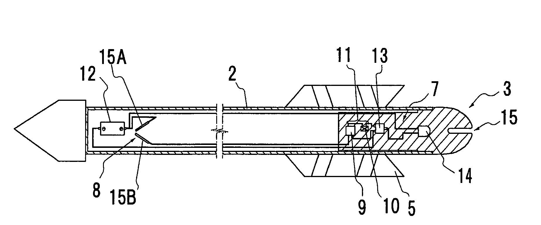
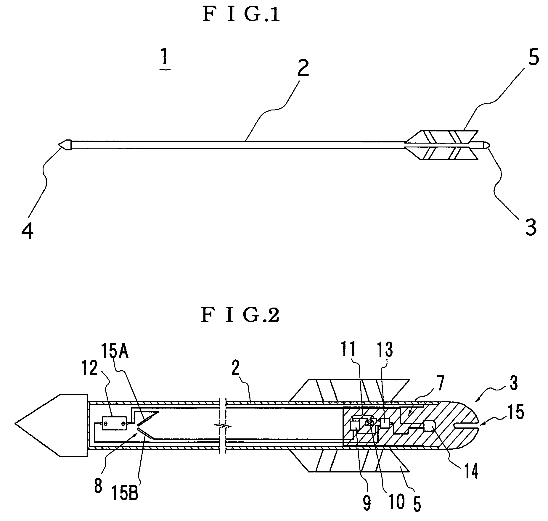
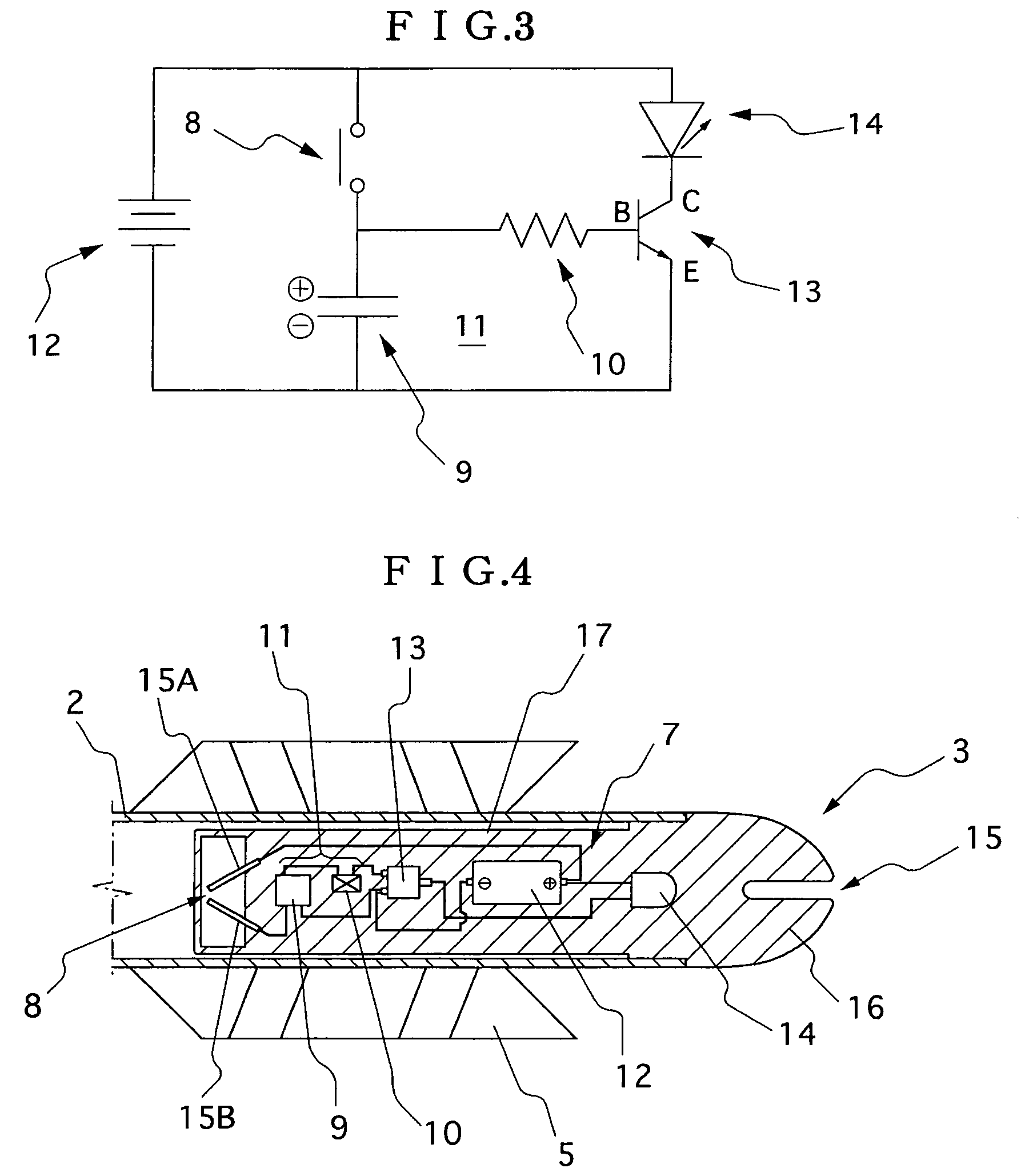
[0037]FIG. 1 is a side explanatory view showing an example of an arrow with a light emitting function to which the invention is applied, FIG. 2 is an explanatory view showing the internal mechanism of FIG. 1, and FIG. 3 shows an electrical circuit of FIG. 2.

[0038]The arrow 1 shown herein includes a nock 3 attached to the rear end of an arrow shaft 2, an arrowhead 4, and fletchings 5.

[0039]Inside the arrow shaft 2, a light emission control part 7 is installed, and this light emission control part 7 includes an electrical circuit that has an acceleration switch 8, a capacitor circuit 11 composed of a capacitor 9 and a resistor 10, a lithium battery 12, a transistor 13, and an LED element 14.

[0040]Herein, the lithium battery 12 is disposed at the front end side inside the arrow shaft 2, and an acceleration switch 8 is provided at the rear portion...


PUM


Abstract

An arrow is provided with a light emitting function, a nock with a light emitting function, and a light emission control device to be used in an arrow which thereby realize accurate and stable light emission periods of time and a reduction in size and weight of light emitting members by using an electronic circuit with an acceleration sensor switch in its light emission control part. The control device includes an acceleration switch, a capacitor circuit including a capacitor and a resistor, and an electrical circuit installed inside the arrow, nock, or attachable to and detachable from the arrow. Electricity is applied when the arrow is discharged from a bow to emit light for a set period of time.

Description

BACKGROUND OF THE INVENTION[0001]1. Technical Field[0002]The present invention relates to an arrow and nock with a light emitting function. More specifically, the present invention relates to an arrow with a light emitting function, a nock with a light emitting function, and a light emission control device to be used in the arrow, which make it possible for a shooter to confirm whether an arrow discharged by the shooter hit the target or not.[0003]2. Background Art[0004]As sports and games for discharging arrows toward targets, there is kyudo, archery, bowgun (crossbow), darts, etc.[0005]For example, kyudo is normally divided into near-target events with a shooting distance of 28 m and distant-target events with a shooting distance of 60 m, and in both events, a circular target is shot by an arrow.[0006]In archery, mainly, an 18 m shooting distance is set for indoor games, and for outdoor games, 30 m, 50 m, and 90 m shooting distances are set.[0007]Dart games are made competitive by...

Claims


Application Information

Patent Timeline
Patent Type & Authority Patents(United States)
IPC IPC(8): F42B6/04A63B65/00A63B69/00F42B12/38
CPCA63B65/00F42B12/382A63B2207/02A63B2225/74
Inventor TAKAHASHI, YASUHIRO
Owner TAKAHASHI YASUHIRO
Why Eureka
Try Eureka