Neural stimulation system providing auto adjustment of stimulus output as a function of sensed impedance

a neural stimulation and output amplitude technology, applied in the field of neural stimulation systems, can solve the problems of insufficient evoked stimulus, more likely to be painful stimulus, and more likely to be over-stimulated, so as to minimize the occurrence of over-stimulation or under-stimulation, reduce the occurrence of over-stimulation, and achieve comfortable and effective paresthesia

Inactive Publication Date: 2008-01-08
BOSTON SCI NEUROMODULATION CORP
View PDF41 Cites 484 Cited by
  • Summary
  • Abstract
  • Description
  • Claims
  • Application Information

AI Technical Summary

Benefits of technology

[0011]As indicated above, the present invention uses the measured impedance as an indicator of stimulation energy delivered from the electrode or electrodes to the target neural tissue. The measurement of impedance changes between the stimulation electrodes or neighboring electrodes provides a relative quantitative measure of the electrode array's theoretical effectiveness in providing therapeutic stimulation. The relative change in the measured impedance provides information on the ability of electrical current to flow to the neural tissue. Knowledge of the measured impedance with respect to time allows for the system to effectively auto correct the output amplitude, thereby minimizing the occurrence of over-stimulation or under-stimulation.
[0012]One application for the present invention is for a Spinal Cord Stimulation (SCS) system that automatically corrects or adjusts the stimulation amplitude in order to maintain a comfortable and effective paresthesia. As postural change, lead array movement, scar tissue maturation, and the like occur, allowing more energy from the emitting electrode or electrodes of the SCS system to be delivered to the neural tissue, the more likely over-stimulation occurs. Conversely, as events occur that attenuate the coupled energy, the more likely a desired paresthesia does not occur (under stimulation). The relative change in measured impedance is used as a measure of the stimulation energy delivered to the neural tissue. Availability of the measured impedance changes with respect to time allows the system to effectively auto correct the stimulation output amplitude, thereby minimizing the occurrence of over-stimulation (excessive-threshold paresthesia) or under-stimulation (sub-threshold paresthesia).
[0013]In accordance with one aspect of the invention, there is provided a neural stimulation system having means for measuring the impedance changes between selected electrodes that occur over time in the epidural space where the electrodes are positioned to be in close proximity to the dura mater of the spinal cord. The system also can provide means for correlating the change in impedance with downward or upward adjustment of stimulation energy. Alternatively, the morphology of the impedance resulting from an event, such as a postural movement may be correlated with the corrective adjustments to stimulation energy. Based on this predetermined correlation, relative impedance changes of significance, i.e., changes indicating that over-stimulation or under-stimulation is likely to occur, are used as triggers to automatically make adjustments, or corrections, in the amplitude of the stimulus current to prevent painful over-stimulation or sub-threshold under-stimulation.
[0015]By way of another example, a rapidly changing impedance variation would likely indicate an acute movement of the electrode array surface contact from the proximity of the dura mater. Such a rapid change could be due to a postural change causing the electrode array to move with respect to its location in the epidural space. In accordance with the present invention, when a significant change in average or other weighted measure of impedance, e.g., 10-15%, occurs over a relatively short period of time, e.g., over 10-20 minutes, then such change triggers a corresponding change in the magnitude of the stimulus output in order to maintain a desired therapeutic effect, e.g., to minimize sub-threshold stimulation or painful over stimulation.

Problems solved by technology

Thus, as an event occurs, such as a postural change, lead array movement, or scar tissue maturation, that allows more energy to couple from the emitting electrode or electrodes to the neural tissue, the more likely the stimulus will be painful, i.e., the more likely over-stimulation will occur.
Conversely, as an event occurs that attenuates the coupled stimulation energy, the more likely the stimulus will not be sufficient to evoke the desired therapeutic effect (under stimulation).

Method used


Image

  • Neural stimulation system providing auto adjustment of stimulus output as a function of sensed impedance
  • Neural stimulation system providing auto adjustment of stimulus output as a function of sensed impedance
  • Neural stimulation system providing auto adjustment of stimulus output as a function of sensed impedance

Examples


Embodiment Construction

[0029]The following description is of the best mode presently contemplated for carrying out the invention. This description is not to be taken in a limiting sense, but is made merely for the purpose of describing the general principles of the invention. The scope of the invention should be determined with reference to the claims.

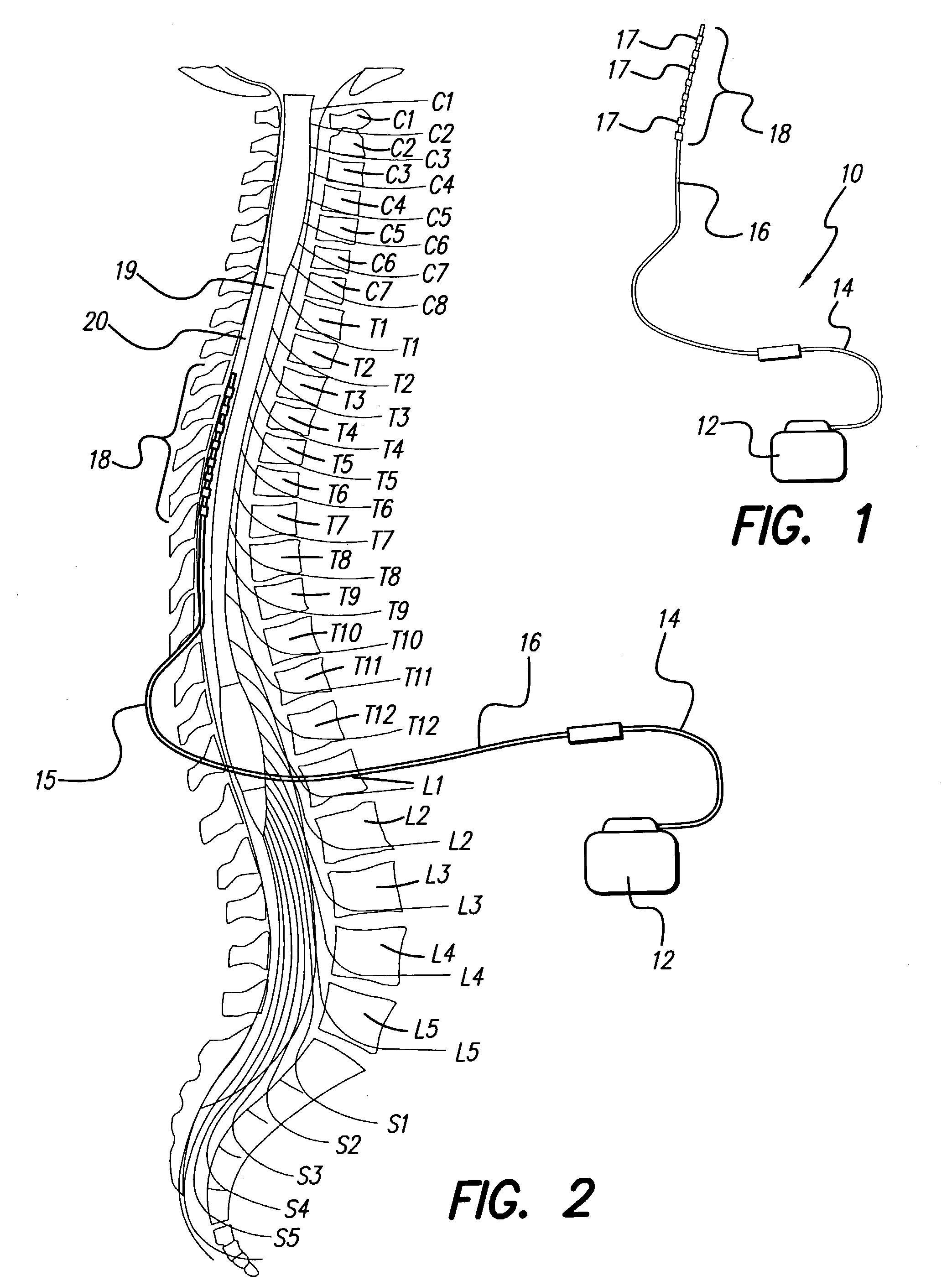
[0030]A representative neural stimulation system 10 is shown in FIG. 1. Such a system typically comprises an Implantable Pulse Generator (IPG) 12, a lead extension 14, an electrode lead 16, and an electrode array 18. The electrode array includes a plurality of electrode contacts 17 (also referred to as “electrodes”). The electrodes 17 are arranged, for example, in an in-line array 18 near the distal end of the lead 16. Other electrode array configurations may also be used. The IPG 12 generates stimulation current pulses that are applied to selected ones of the electrodes 17 within the electrode array 18.

[0031]A proximal end of the lead extension 14 is remova...


PUM


Abstract

A neural stimulation system automatically corrects or adjusts the stimulus magnitude (stimulation energy) in order to maintain a comfortable and effective stimulation therapy. Because the changes in impedance associated with the electrode-tissue interface can indicate obstruction of current flow and positional lead displacement, lead impedance can indicate the quantity of electrical stimulation energy that should be delivered to the target neural tissue to provide corrective adjustment. Hence, a change in impedance or morphology of an impedance curve may be used in a feedback loop to indicate that the stimulation energy needs to be adjusted and the system can effectively auto correct the magnitude of stimulation energy to maintain a desired therapeutic effect.

Description

[0001]This application claims the benefit of U.S. Appl. Ser. No. 60 / 357,008, filed Feb. 12, 2002, which application is herein incorporated by reference. This application is also related to U.S. Appl. Ser. No. 10 / 364,434 (now U.S. Pat. No. 7,239,920) U.S. Appl. Ser. No. 10 / 364,437 (now abandoned), both filed Feb. 11, 2003. The entire disclosures of the above applications are expressly incorporated herein by reference.BACKGROUND OF THE INVENTION[0002]The present invention relates to neural stimulation systems and, more particularly, to an output control system used with such neural systems that automatically maintains the output of the stimulation system at a comfortable and efficacious level.[0003]The present invention may be used in various stimulation therapies in which a neurostimulator is used to stimulate neural tissue. One example where the present invention may be employed is with stimulation of peripheral nerves, e.g., the nerves in the arms, legs, fingers, which nerves are d...

Claims


Application Information

Patent Timeline
Patent Type & Authority Patents(United States)
IPC IPC(8): A61N1/00
CPCA61N1/3615A61N1/36139A61N1/36071A61N1/08
Inventor KING, JOHN D HTHACKER, JAMES R
Owner BOSTON SCI NEUROMODULATION CORP
Why Eureka
Try Eureka