
Vehicle telematics system

a technology of vehicle telematics and telematics, applied in the field of vehicle telematics system, can solve the problems of lack of advanced power management functionality, inability to quickly identify performance problems, or more accurately, inability to use data transmitted to the remote location, etc., and achieve the effect of facilitating vehicle identification and saving power

Active Publication Date: 2008-01-08
HALDEX BRAKE PROD LTD
View PDF13 Cites 95 Cited by
  • Summary
  • Abstract
  • Description
  • Claims
  • Application Information

AI Technical Summary

Benefits of technology

Enables effective remote diagnostics, compares vehicle performance with others, conserves power, and identifies inactive vehicles, enhancing fleet management and operator performance monitoring.

Problems solved by technology

However, vehicles have traditionally performed such monitoring typically only for the vehicle driver and without communication of any impending results, problems and / or vehicle malfunction to a remote site for trouble-shooting, diagnosis or prognostics.
By tracking the vehicle, performance problems can be quickly identified.
It is often difficult, particularly when an entity maintains a large fleet of trailers, to keep track of the locations of each of the trailers in the fleet.
While the above-described prior art systems do provide global positioning system (GPS) satellite tracking and wireless communications for remote diagnostics, they suffer from a number of disadvantages.
One of such disadvantages relates to the manner in which the systems communicate with the various vehicle systems.
While this information is often pertinent to performing system diagnostics and prognostics, none of the prior art systems described above is communicable over the CAN bus, and therefore the pertinent information communicated over the CAN bus is not transmitted to the remote location for use in the diagnostics and / or prognostics.
Another disadvantage of the systems disclosed in the afore-mentioned prior art references relates to the way in which data transmitted to the remote location is used, or more accurately, not used.
A further disadvantage of the systems disclosed in the afore-mentioned prior art references relates to the lack of advanced power management functionality.
As should be obvious to one skilled in the art, any system for providing tracking and wireless communications for remote diagnostics of a vehicle will consume power.
Also as should be obvious to one skilled in the art, the vehicle in which such a system operates only has a limited supply of power at its disposal.
It is undesirable from both cost management and space management standpoints to provide large power supplies for the systems to operate, and as such, advanced power management is critical, particularly when the trailer is parked and disconnected from a tractor.
Still another disadvantage of the systems disclosed in the afore-mentioned prior art references relates to the fact that none are particularly directed to managing a fleet of commercial vehicles where lack of movement of the vehicle for a relatively long duration is particularly important.
None of the systems described above provide any functionality for facilitating the identification of such “slow movers.”

Method used


Image

  • Vehicle telematics system
  • Vehicle telematics system
  • Vehicle telematics system

Examples


Embodiment Construction

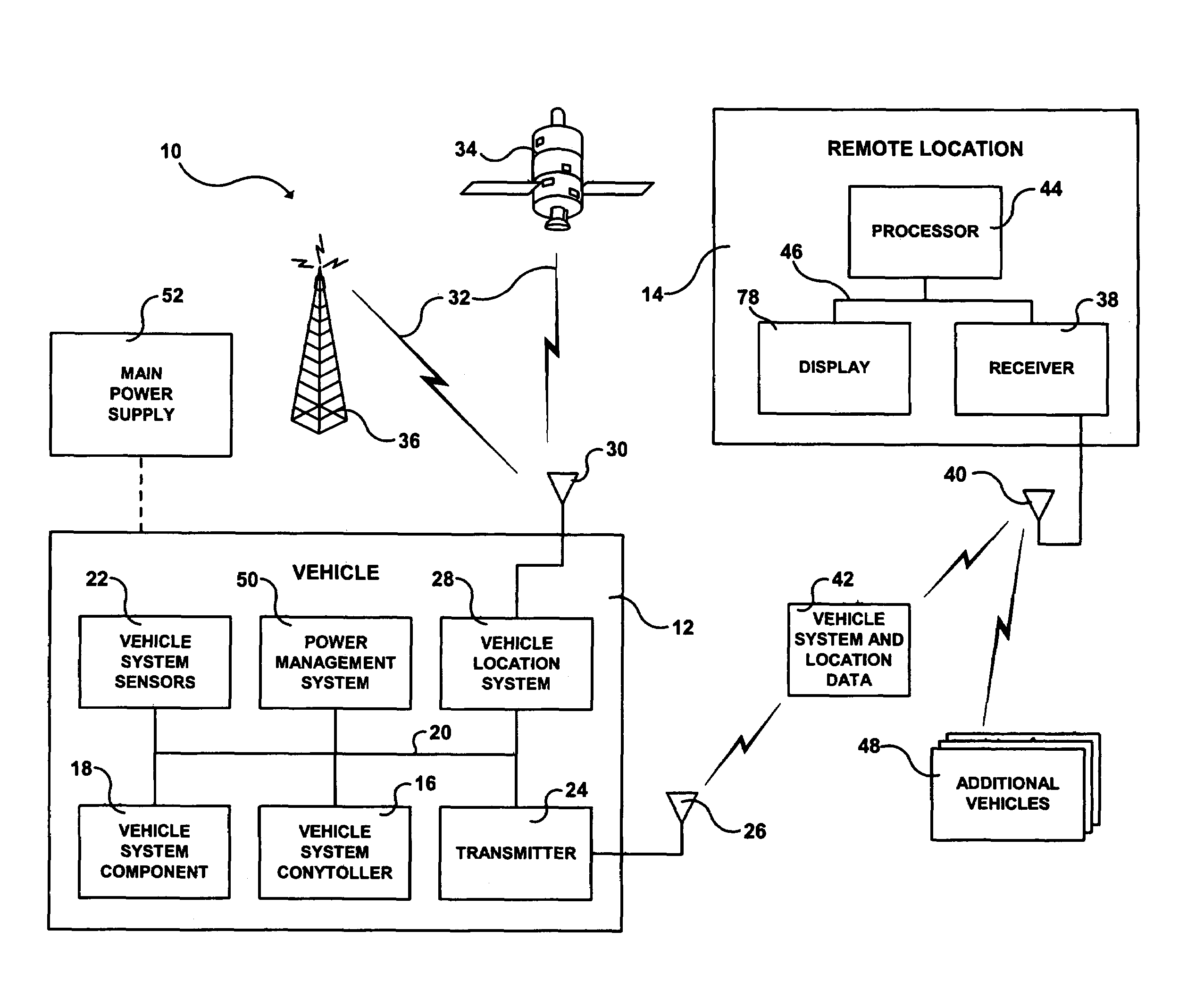
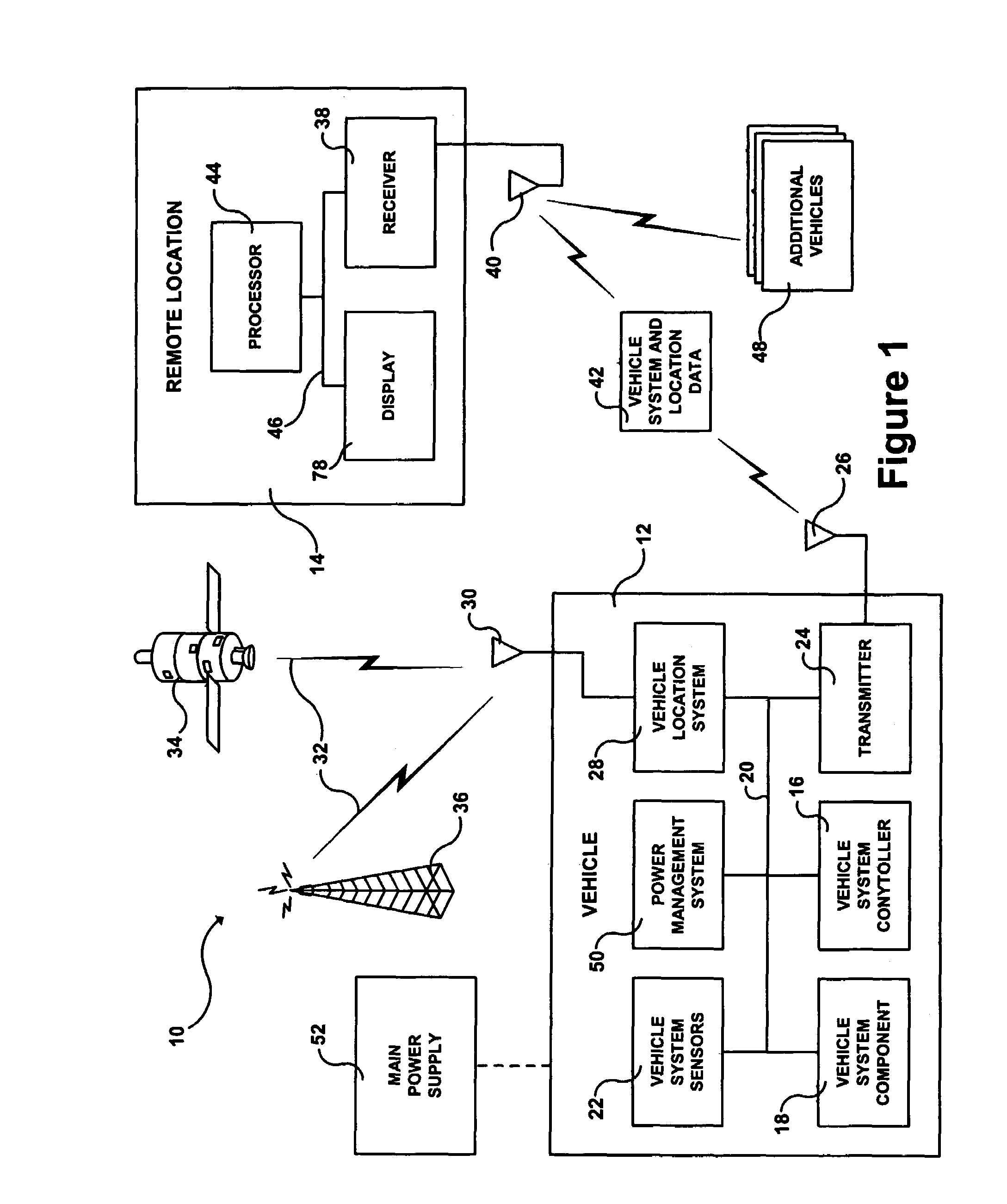
[0031]Referring first to FIG. 1, a system 10 for wireless transmission of vehicle data from a vehicle 12 to a remote location 14 is shown. The vehicle 12 includes a vehicle system controller 16, at least one vehicle system component 18 adapted to be controlled by the vehicle system controller 16, and a communications link 20 connecting the vehicle system controller 16 with the vehicle system component(s) 18. The vehicle system controller 16 and the vehicle system component(s) 18 communicate vehicle system data between one another via the communications link 20.

[0032]Examples of vehicle systems which may be controlled include an electronic brake system (EBS), an antilock brake system (ABS), a suspension system, a traction control system, an anti-slip regulation (ASR) system, a steering system, a stability control system, an electronic stability program (ESP), an adaptive cruise control (ACC) system, a diagnostics system, a trailer interface system, a transmission system, an air manag...


PUM


Abstract

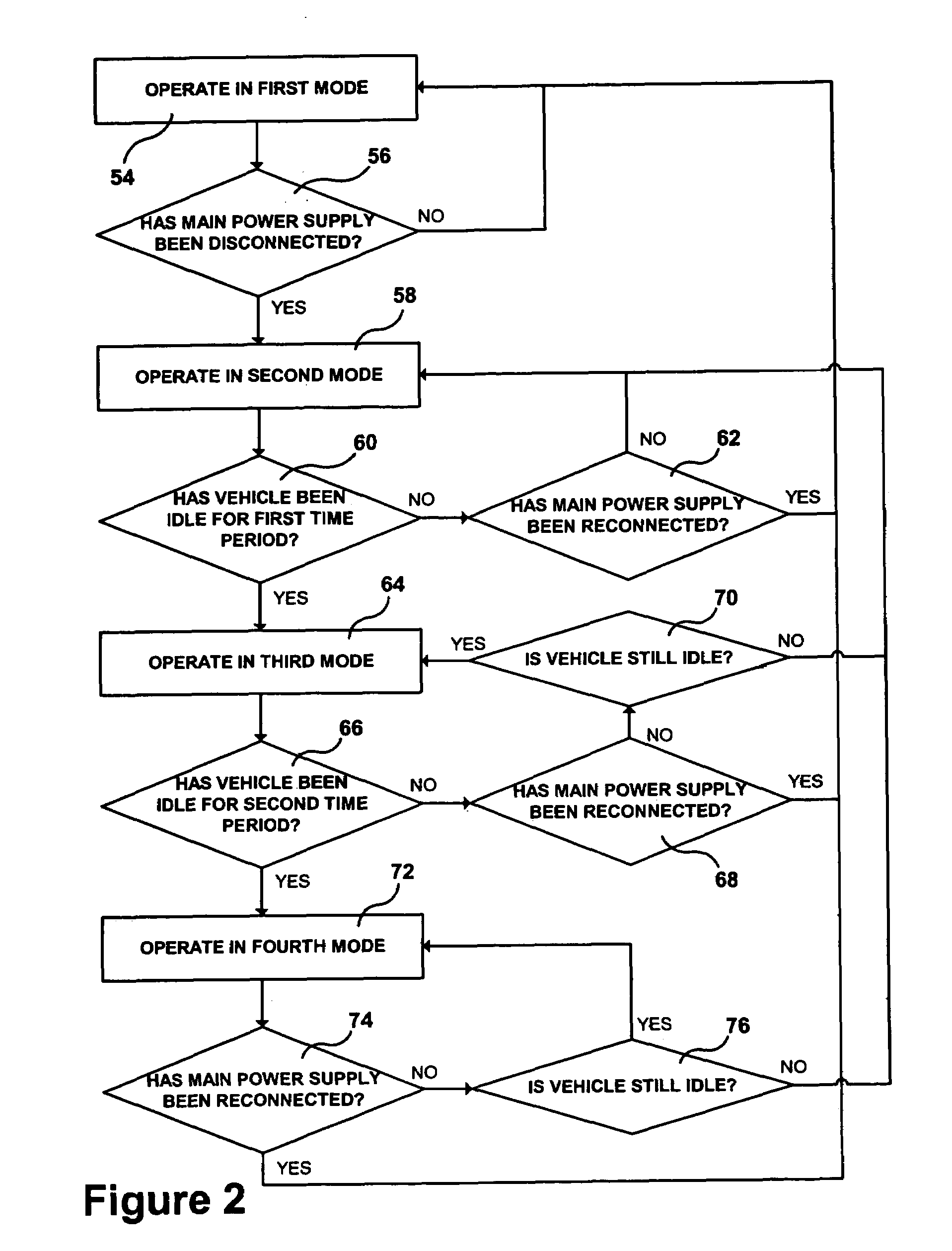
Disclosed is a system providing tracking and wireless communications for remote diagnostics of a vehicle which transmits data communicated over a vehicle system's CAN bus to a remote location, which is adapted to use data received from a vehicle in order to compare the performance of the vehicle and / or of the operator of the vehicle with the performance of other vehicles and / or operators of other vehicles, which incorporates advanced power management functionality for conserving power, particularly when the system is disconnected from a main power supply, and which facilitates the identification of vehicles that have not reported back to the system or that have not moved within a specified time period.

Description

FIELD OF THE INVENTION[0001]The present invention relates to methods and apparatus for diagnosing components in a vehicle and transmitting data relating to the diagnosis of the components in the vehicle and other information relating to the operating conditions of the vehicle, as well as the geographical position of the vehicle, to one or more remote locations distant from the vehicle, particularly via a telematics link.BACKGROUND OF THE INVENTION[0002]Generally, a telematics system refers to a system that combines telecommunications and information processing. More specifically, the term has evolved to refer to automobile systems that combine global positioning system (GPS) satellite tracking and wireless communications for automatic roadside assistance and remote diagnostics. This combination provides consumers with a multitude of services not previously available as described more fully below.[0003]Communications between a vehicle and a remote assistance facility are important fo...

Claims


Application Information

Patent Timeline
Patent Type & Authority Patents(United States)
IPC IPC(8): G06F7/00G06F1/32G06F19/00G07C5/00G08G1/123
CPCG06F1/3203G06F1/3228G07C5/008G08G1/20
Inventor WOOLFORD, PAULCARLSSON, ROGER
Owner HALDEX BRAKE PROD LTD
Learn More