Method of regulating wireless sensor network energy use

a wireless sensor and energy use technology, applied in frequency-division multiplex, instruments, fire alarms, etc., can solve the problem of limited power source of sensor nodes

Active Publication Date: 2008-01-08
DEERE & CO
View PDF16 Cites 58 Cited by
  • Summary
  • Abstract
  • Description
  • Claims
  • Application Information

AI Technical Summary

Problems solved by technology

In contrast, the sensor nodes have a limited available power source, e.g., battery, and in turn, limited transmission power.

Method used


Image

  • Method of regulating wireless sensor network energy use
  • Method of regulating wireless sensor network energy use
  • Method of regulating wireless sensor network energy use

Examples


Embodiment Construction

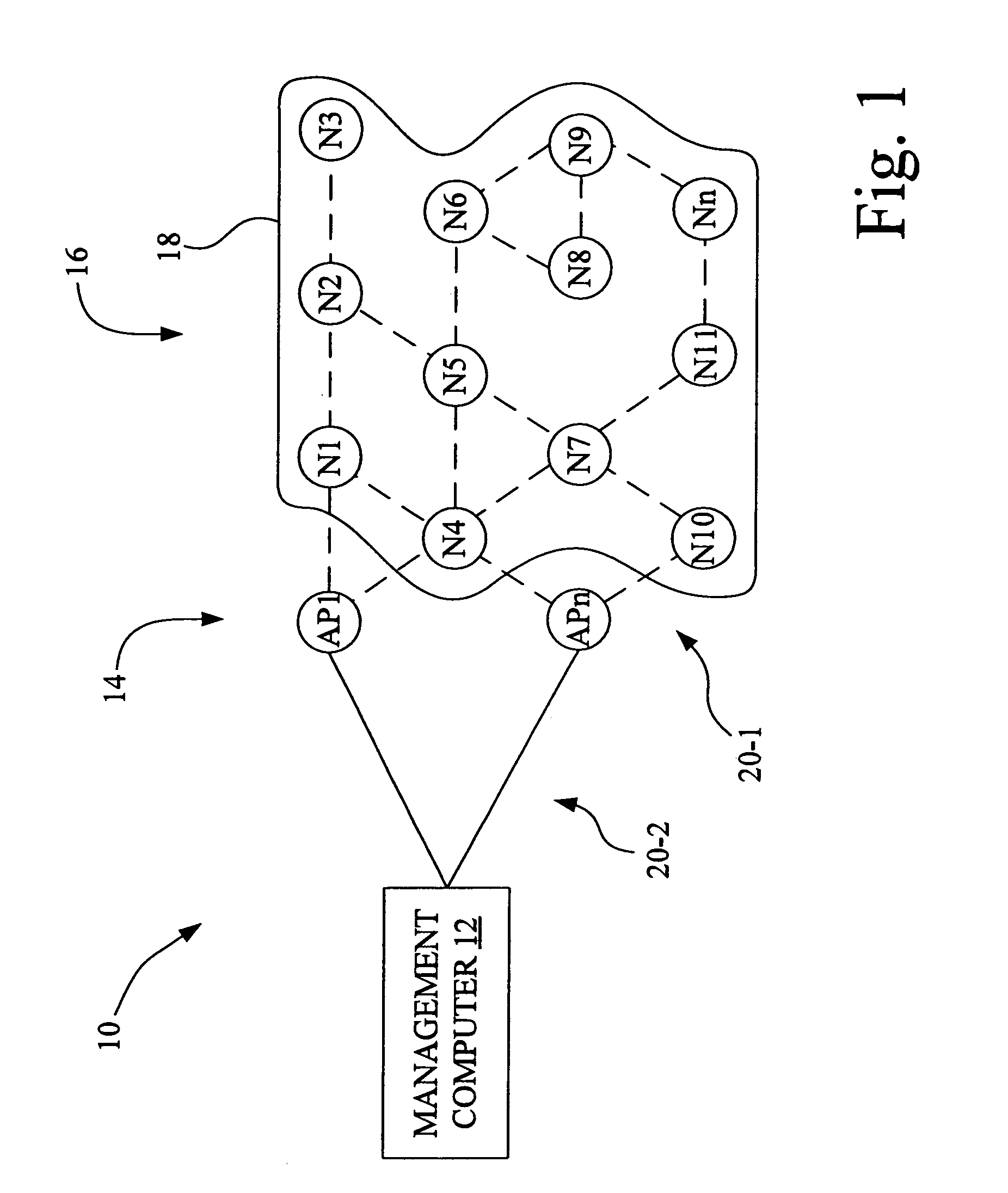
[0013]Referring now to the drawings, there is shown in FIG. 1 a diagrammatic representation of an exemplary wireless sensor network 10 in accordance with an embodiment of the present invention. Network 10 may be, for example, an ad hoc network, and includes a management computer 12, a plurality of access nodes (AP) 14 and a plurality of sensor nodes (N) 16. The plurality of access nodes 14 are individually identified as access point nodes AP1, . . . APn, wherein n is an integer.

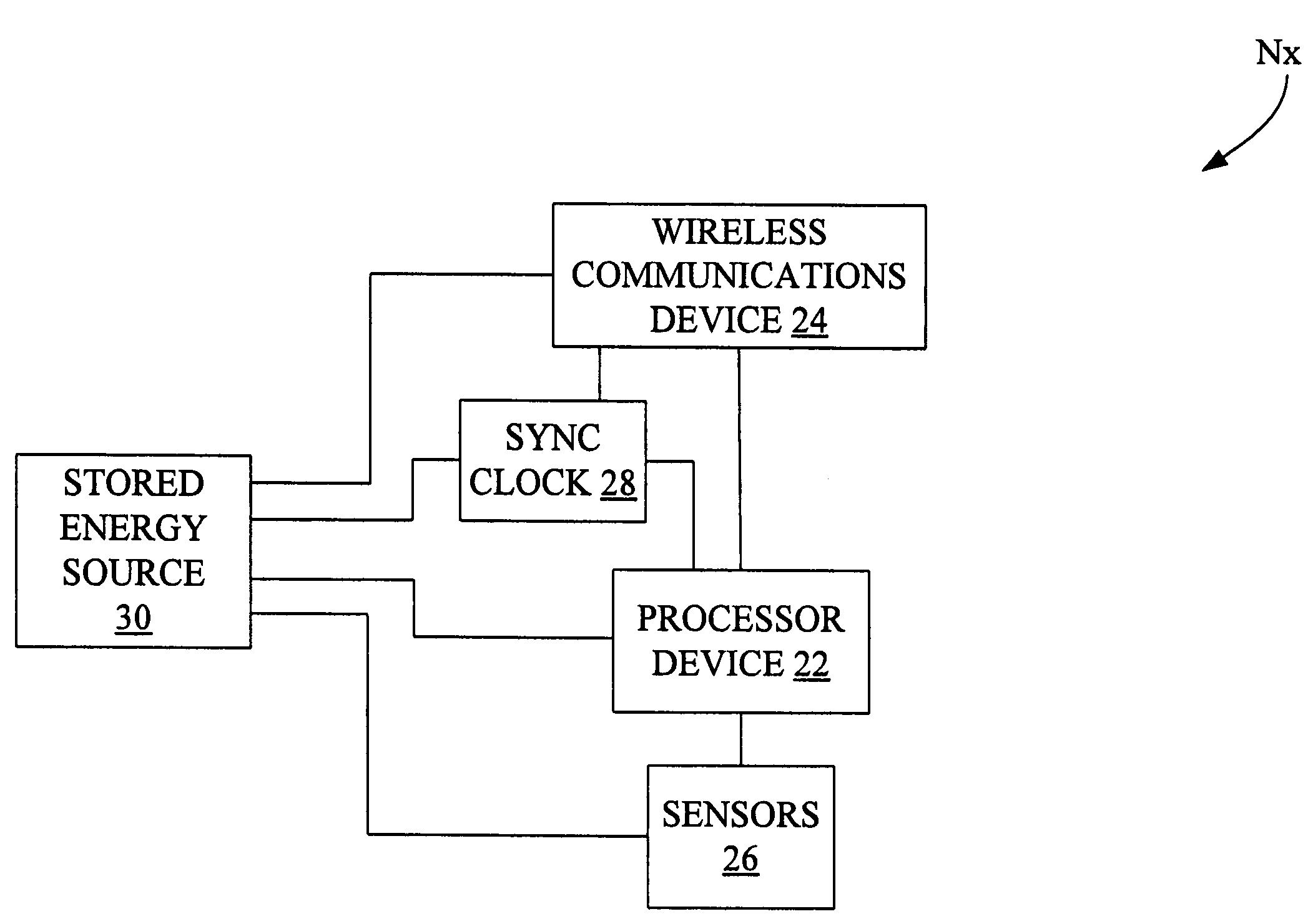
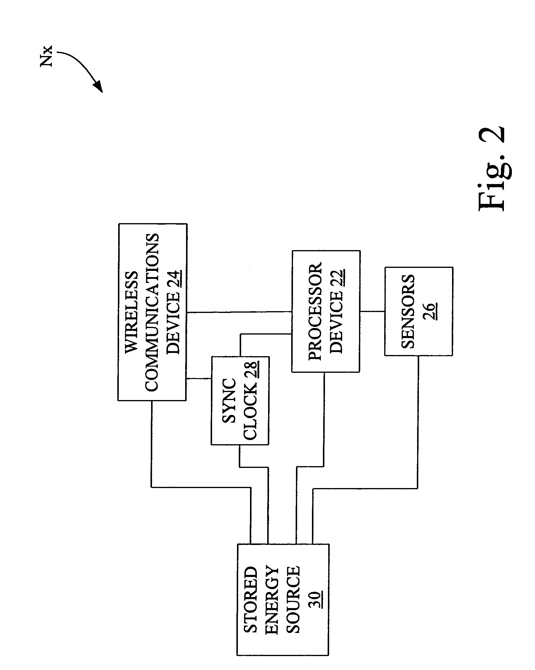
[0014]The plurality of sensor nodes 16 are positioned over a sensing region 18, and are individually identified as sensor nodes N1, N2, . . . Nn. Sensor node Nn represents the nth sensor node positioned in sensing region 18, wherein n is an integer. Any particular node Nx (where x is from 1 to n) of the plurality of sensor nodes 16 is able to communicate with one or more other sensor nodes, so as to form multi-hop paths to one or more of the AP nodes 14. Wireless communications paths 20-1 are established bein...


PUM


Abstract

A method of regulating wireless sensor network energy use includes establishing a wireless sensor network having at least one access point node, and having a plurality of sensor nodes defining a sensing region; identifying at least one environment parameter related to an environment of the sensing region that is needed to make an operational decision; and adjusting data collection from the plurality of sensor nodes based on the at least one environment parameter to adjust a power consumption of at least one sensor node of the plurality of sensor nodes.

Description

FIELD OF THE INVENTION[0001]The present invention is related to wireless sensor networks, and more particularly, to a method of regulating wireless sensor network energy use.BACKGROUND OF THE INVENTION[0002]Wireless sensor networks have been proposed with potential applications, for example, in environmental, surveillance, military, health and security monitoring. Such a network includes a group of sensor nodes, each with one or more sensors, an embedded processor, and a low power receiver / transmitter. Typically, these nodes are linked by a wireless medium to perform distributed sensing tasks.[0003]In one such network, for example, the sensor nodes may form an ad hoc network where communication between two arbitrary nodes may take more than one “hop”, i.e., the message may travel through one or intermediate nodes rather than via a direct transmission. The ad hoc network typically has one or more access point (AP) nodes that have greater energy availability and can transmit data to t...

Claims


Application Information

Patent Timeline
Patent Type & Authority Patents(United States)
IPC IPC(8): G08C19/16
CPCH04W52/0219A01G1/001G01D21/00A01G25/167H04W84/18
Inventor ANDERSON, NOEL WAYNE
Owner DEERE & CO
Why Eureka
Try Eureka