
Synthetic jet based medicament delivery method and apparatus

a technology of medicament delivery and synthetic jet, applied in the direction of packaging, other medical devices, coatings, etc., can solve the problems of large clusters reaching the deep lungs, reducing the percentage of drugs available to patients for absorption, and another level of uncertainty

Active Publication Date: 2008-01-15
MICRODOSE THERAPEUTX INC
View PDF37 Cites 117 Cited by
  • Summary
  • Abstract
  • Description
  • Claims
  • Application Information

AI Technical Summary

Benefits of technology

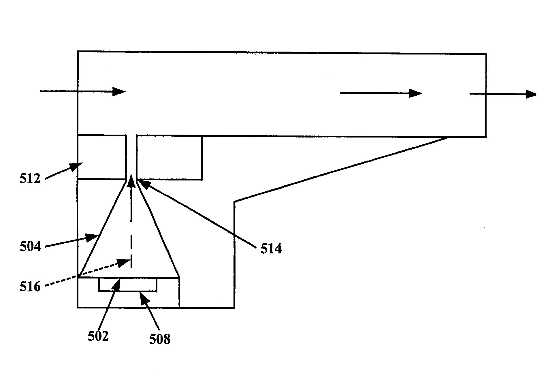
[0023]The present invention provides a dry powder inhaler which employs synthetic jetting technology to aerosolize drug powder from a blister pack or the like. Synthetic jetting is not new. It was discovered at least as early as 1950 that if one uses a chamber bounded on one end by an acoustic wave generating device and bounded on the other end by a rigid wall with a small orifice, that when acoustic waves are emitted at high enough frequency and amplitude from the generator, a jet of air that emanates from the orifice outward from the chamber can be produced. See, for example, Ingard and Labate, Acoustic Circulation Effects and the Nonlinear Impedance of Orifices, The Journal of the Acoustical Society of America, March 1950. The jet, or so-called “synthetic jet”, is comprised of a train of vortical air puffs that are formed at the orifice at the generator's frequency. However, the use of a synthetic jet to deaggregate and eject a dry-powder material from a blister pack or the like in a dry powder inhaler is new, and provides advantages over prior art dry powder inhalers.

Problems solved by technology

(1) Small size particles develop an electrostatic charge on themselves during manufacturing and storage. This causes the particles to agglomerate or aggregate, resulting in clusters of particles which have an effective size greater than 5 microns. The probability of these large clusters making it to the deep lungs then decreases. This in turn results in a lower percentage of the drug being available to the patient for absorption.
(2) The amount of active drug that needs to be delivered to the patient may be of the order of tens of micrograms. Since current powder filling equipment cannot effectively deliver aliquots of drugs in microgram quantities with acceptable accuracy, the standard practice is to mix the active drug with a filler or bulking agent such as lactose. This additive also makes the drug “easy to flow”. In some cases this filler is sometimes called a carrier. These carrier particles are often larger than the drug particles in size. The ability of the dry powder inhaler to separate drug from the carrier is an important performance parameter in the effectiveness of the design.
(3) Active drug particles with sizes greater than 5 microns will be deposited either in the mouth or throat. This introduces another level of uncertainty since the bioavailability and absorption of the drug in these locations is different from the lungs. Dry powder inhalers need to minimize the drug deposited in these locations to reduce the uncertainty associated with the bioavailability of the drug.
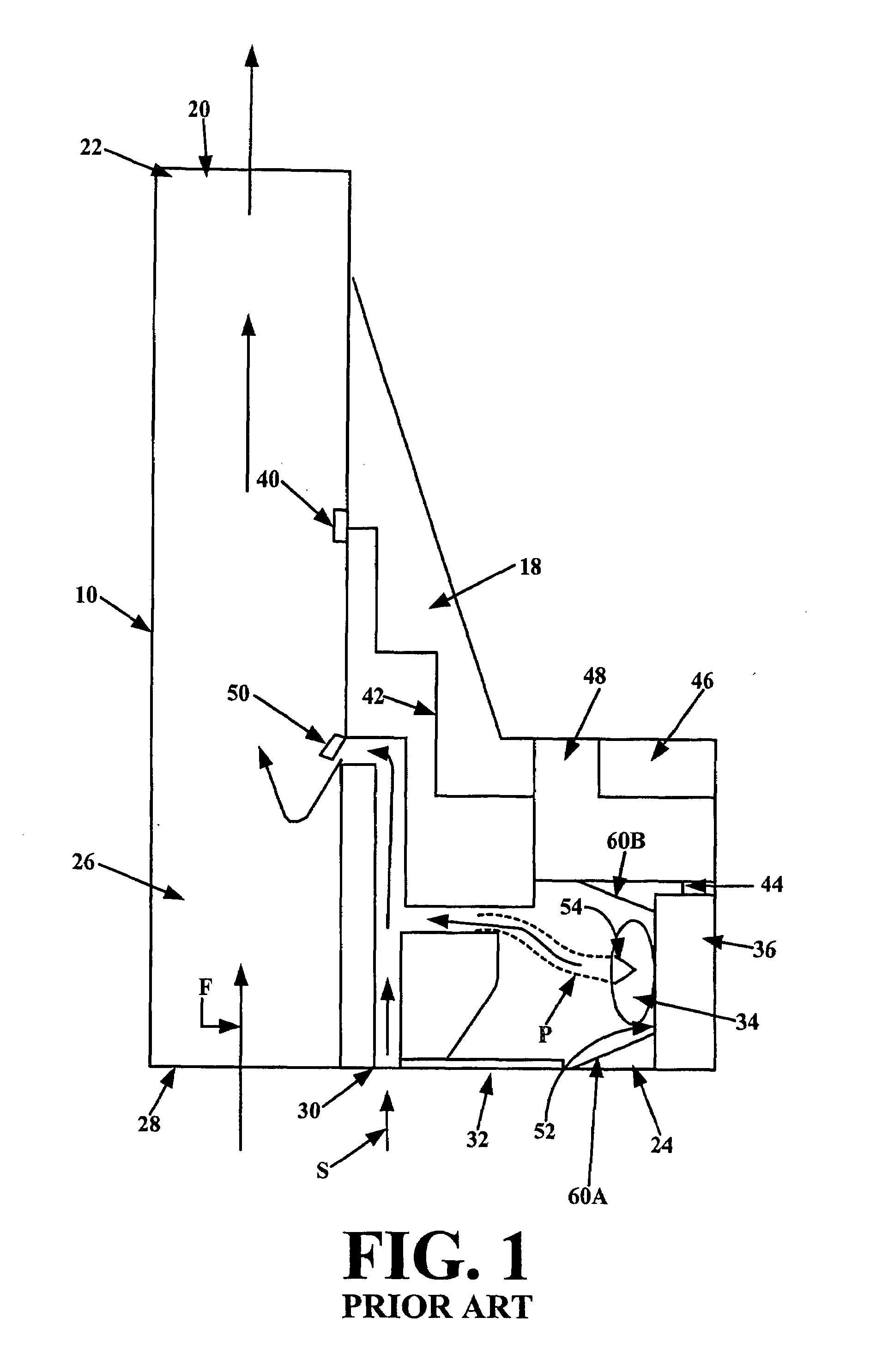
These prior art devices present several problems and possess several disadvantages.
For instance, these prior art devices require that the user exert considerable effort in inhalation to effect dispensing or withdrawal of powder from a pierced capsule into the inhaled air stream.
With these prior art devices, suction of powder through the pierced holes in the capsule caused by inhalation generally does not withdraw all or even most of the powder out of the capsule, thus causing a waste of the medication.
Also, such prior art devices may result in uncontrolled amounts or clumps of powdered material being inhaled into the user's mouth, rather than a constant inhalation of controlled amounts of finely dispersed powder.
The prior art devices have a number of disadvantages which makes them less than desirable for the delivery of dry powder to the lungs.
Some of these disadvantages are:The performance of the prior art inhalers depends on the flow rate generated by the user.
Lower flow rate does not result in the powder being totally deaggregated and hence adversely affects the dose delivered to the patient.Inconsistency in the bioavailability of the drugs from dose-to-dose because of lack of consistency in the deaggregation process.Large energy requirements for driving the electromechanical based inhalers which increases the size of the devices making them unsuitable for portable use.Loss of medication from opened or topped capsules.Deterioration of medication in open or topped capsules due to exposure to oxygen or moisture.

Method used


Image

  • Synthetic jet based medicament delivery method and apparatus
  • Synthetic jet based medicament delivery method and apparatus
  • Synthetic jet based medicament delivery method and apparatus

Examples


Embodiment Construction

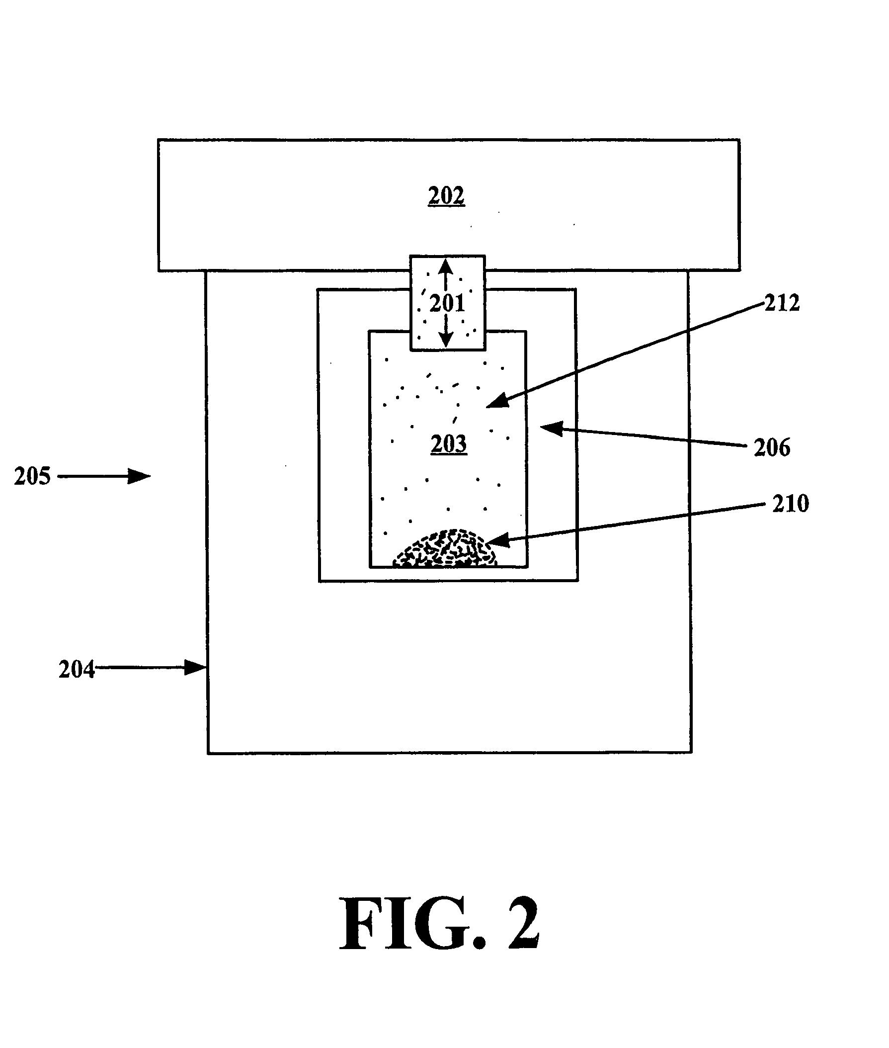
[0037]Referring to FIG. 2, in bare essentials an inhaler 205 in accordance with the present invention comprises a vibrator, e.g., a piezoelectric element 204, a first chamber 203 and a second chamber 202 connected via a passageway 201. The passageway 201 is sized and shaped such that a reciprocating or oscillatory movement of the vibrator coupled to or forming a wall of the first chamber causes the gas in the first chamber to move back and forth through the passageway 201, such that essentially the same mass of gas is moved in each direction, while vortices of the gas are formed at the exits of the passageway 201 such that there is a net flow of gas away from the outlet end of passageway 201, i.e., a synthetic jet of gas is created by the vortices. A vibrator 204, which is operatively connected either directly to the first chamber or via a closed gas tube 206, creates vibrations in the chamber which generate the synthetic jet at the outlet end of passageway 201. The dry powder 210 i...


PUM


Abstract

A dry powder inhaler consisting of first chamber having an orifice for holding a dry powder and a gas, and a second chamber for receiving a deaggregated form of the dry powder and for communicating the deaggregated dry powder to a user. A synthetic jet drives the dry powder from the first chamber to the second chamber.

Description

CROSS REFERENCE TO RELATED APPLICATION[0001]This application claims priority to co-pending U.S. Provisional Application entitled “Synthetic Jet Based Medicament Delivery Method and Apparatus”, having Ser. No. 60 / 547,323, Filed Feb. 24, 2004 which is entirely incorporated herein by reference.FIELD OF THE INVENTION[0002]The present invention relates generally to the field of metering, packaging and delivery of pharmaceuticals and drugs. Particular utility for the present invention is found in delivery of metered and packaged dry powder medications and drugs for inhalation therapy and will be described in connection with such utility, although other utilities are contemplated, including liquid medication applications.DISCUSSION OF THE PRIOR ART[0003]Certain diseases of the respiratory tract are known to respond to treatment by the direct application of therapeutic agents. As these agents are most readily available in dry powdered form, their application is most conveniently accomplishe...

Claims


Application Information

Patent Timeline
Patent Type & Authority Patents(United States)
IPC IPC(8): A61M16/00A61M15/00
CPCA61M15/0028A61M15/0085A61M2016/0018A61M2202/064A61M15/00
Inventor GUMASTE, ANAND V.BOWERS, JOHN
Owner MICRODOSE THERAPEUTX INC
Learn More