Load measuring device for rolling bearing unit and load measuring rolling bearing unit

a technology of rolling bearing unit and load measurement, which is applied in the direction of force/torque/work measurement apparatus, instruments, transportation and packaging, etc., can solve the problems of increasing the cost of the overall rolling bearing unit, and affecting the stability of the truck. , to achieve the effect of suppressing the generation of revolution slip and lightening the weigh

Active Publication Date: 2008-01-22
NSK LTD
View PDF10 Cites 33 Cited by
  • Summary
  • Abstract
  • Description
  • Claims
  • Application Information

AI Technical Summary

Benefits of technology

[0015]An object of the present invention is to provide a load measuring device for a rolling bearing unit and a load measuring rolling bearing unit, capable of being constructed at a low cost with no trouble with endurance and also measuring one or both of the radial load and the axial load applied to the wheel while assuring a precision required to control. Also, another object of the present invention is to provide a structure that can sense precisely the axial load applied to the rolling bearing unit by using only an output signal of a sensor provided to a rolling bearing unit portion.

Problems solved by technology

In addition, such control cannot prevent the event that the running stability of the truck, or the like becomes worse due to its improper carrying state.
Since a high-precision non-contact type sensor is expensive, it is inevitable that a cost is increased as the overall rolling bearing unit equipped with the load measuring device.
For this reason, in addition to the fact that the load sensor 20 itself is expensive, it is inevitable that a cost of the overall load measuring device for the rolling bearing unit is considerably increased.
Also, in the method set forth in JP-B-62-3365, the rigidity of the outer ring equivalent member must be reduced partially and thus there is such a possibility that it is difficult to assure the endurance of the outer ring equivalent member.

Method used


Image

  • Load measuring device for rolling bearing unit and load measuring rolling bearing unit
  • Load measuring device for rolling bearing unit and load measuring rolling bearing unit
  • Load measuring device for rolling bearing unit and load measuring rolling bearing unit

Examples


first embodiment

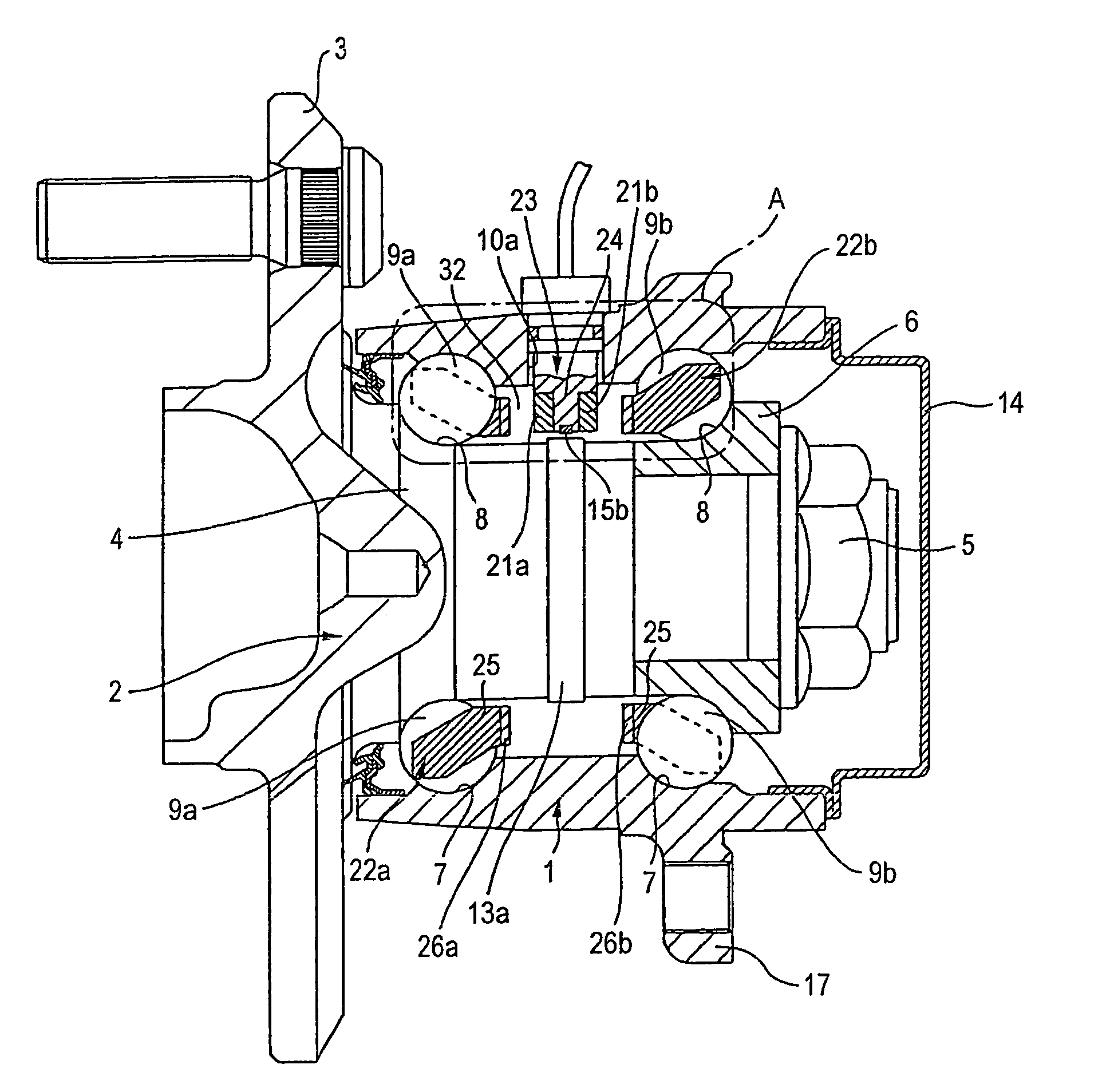
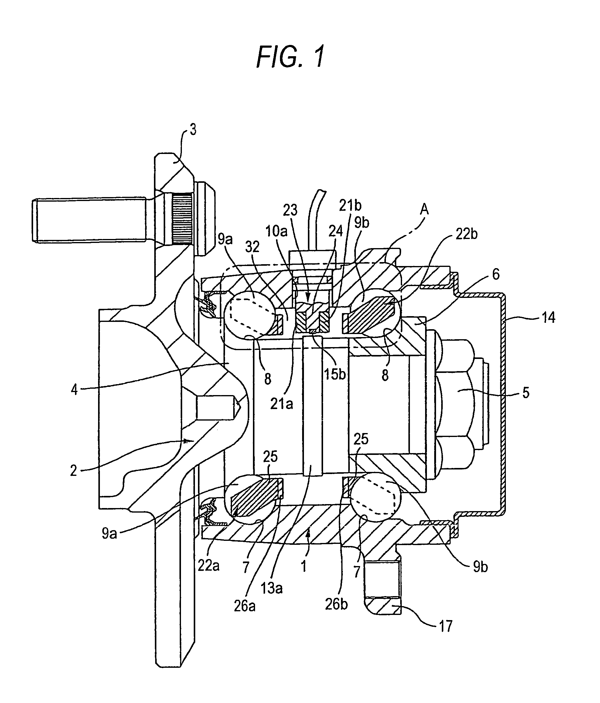
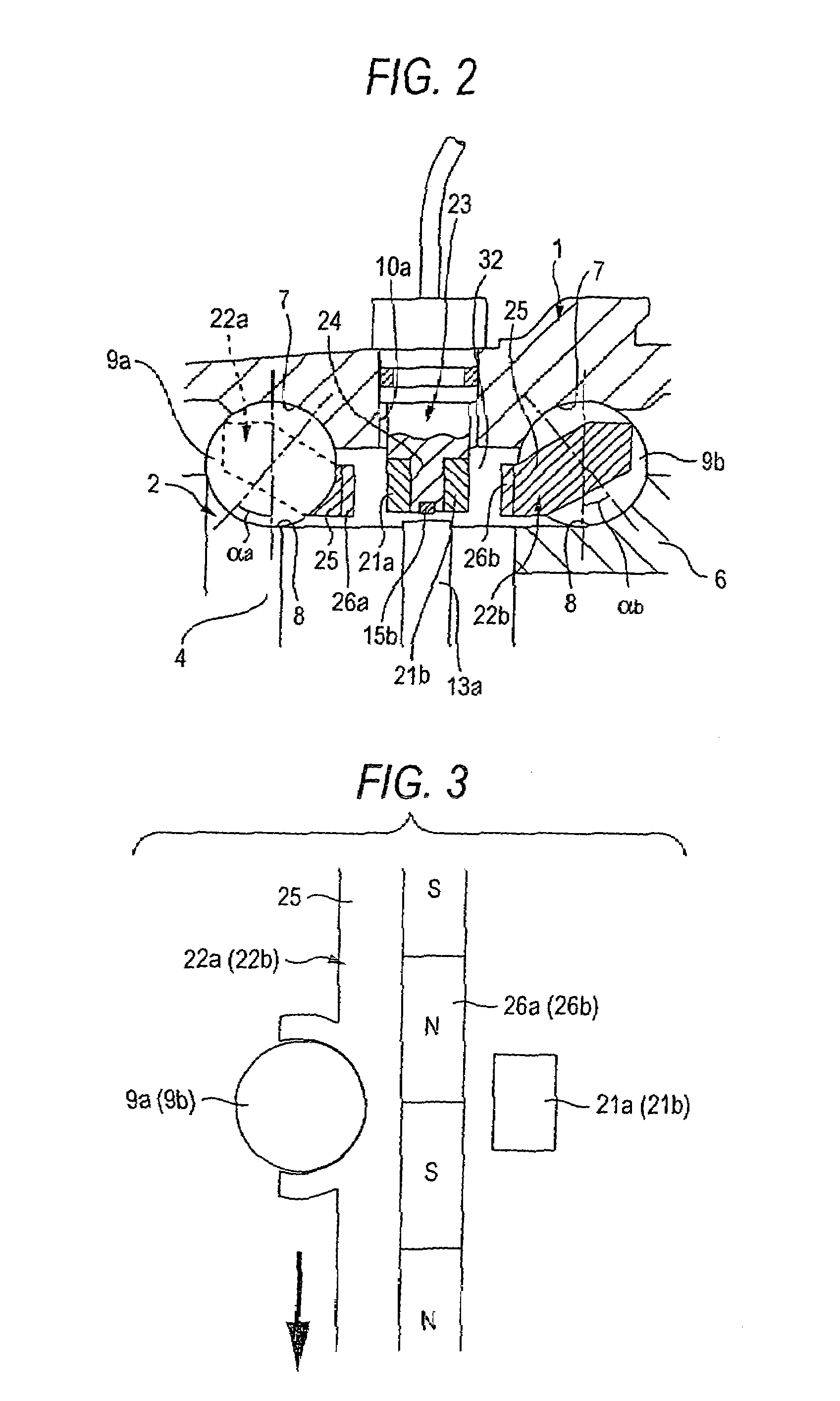
[0124]FIGS. 1 to 3 show s first embodiment of the present invention. The present embodiment shows the case that the present invention is applied to a rolling bearing unit to support idler wheels of the car (front wheels of FR car, RR car, MR car, rear wheels of FF car). Since the structure and the operation of this rolling bearing unit itself are similar to the related-art structure shown in above FIG. 37, their redundant explanation will be omitted or simplified by affixing the same reference symbols to the same portions. Feature portions in the present embodiment will be explained mainly hereinafter.

[0125]The rolling elements (balls) 9a, 9b are rotatably provided in double rows (two rows) respectively between the double row angular contact inner ring raceways 8, 8 and the double row angular contact outer ring raceways 7, 7 in a state that a plurality of rolling elements are held in each row by retainers 22a, 22b respectively. Such inner ring raceways 8, 8 are formed on the outer p...

second embodiment

[0183]FIG. 17 shows a second embodiment of the present invention. In the present embodiment, even though the revolution speed encoder 26a (also the revolution speed encoder 26b shown in FIGS. 1 and 2) is eccentrically moved, the revolution speeds of the rolling elements can be sensed precisely by providing a plurality of revolution speed sensors 21a1, 21a2 (two in FIG. 17). Therefore, in the case of the present embodiment, the revolution speed sensors 21a1, 21a2 are arranged to deviate from the revolution direction of the rolling elements 9a, 9b (see FIG. 1) whose revolution speeds are to be sensed. More particularly, the revolution speed sensors 21a1, 21a2 are arranged in opposite positions with respect to a rotation center O2 of the hub 2 (see FIG. 1) by 180 degree. Then, the present embodiment is constructed to eliminate the influence of an error caused by the eccentric motion of the revolution speed encoder 26a by adding the sensed signals of the revolution speed sensors 21a1, 2...

third embodiment

[0191]In the illustrated example, the case that the revolution speeds of the rolling elements 9a, 9b in double rows are measured as the rotational speeds of the retainers 22a, 22b holding the rolling elements 9a, 9b in double rows is explained. But the revolution speeds of the rolling elements 9a, 9b in double rows can be measured directly. For example, if the magnetic sensors are used as the revolution speed sensors 21a, 21b and the elements made of magnetic material is used as the rolling elements 9a, 9b in double rows, characteristics of the magnetic sensors constituting the revolution speed sensors 21a, 21b are changedwith the revolution of the rolling elements 9a, 9b in double rows (in the case of the active sensor into which the magnetic sensors are incorporated). In other words, a quantity of magnetic flux flowing through the magnetic sensors is increased at an instance when the rolling elements 9a, 9b made of magnetic material are present in vicinity of the sensing surfaces ...


PUM

PropertyMeasurementUnit
contact anglesaaaaaaaaaa
revolution speedsaaaaaaaaaa
rotational speedaaaaaaaaaa

Abstract

Revolution speeds nca, nib of rolling elements 9a, 9b are sensed by a pair of revolution speed sensors 21a, 21b. Also, a rotational speed ni of a hub 2 is sensed by a rotational speed sensor 15b. A sum “nca+ncb” or a difference “nca−nib” the revolution speeds of rolling elements 9a, 9b in double rows is calculated based on sensed signals of the revolution speed sensors 21a, 21b, and then a ratio “nca+nib / ni” or “nca−ncb / ni” of this sum or difference to the rotational speed ni is calculated. Then, the radial load or the an axial load is calculated based on the ratio “nca+ncb / ni” or “ca−nib / ni”.

Description

TECHNICAL FIELD[0001]The present invention relates to a load measuring device for a rolling bearing unit and a load measuring rolling bearing unit, for example, a rolling bearing unit used to support wheels of a mobile body such as a car, a railway vehicle, various carrier cars, and so forth. More particularly, the present invention relates to a load measuring device for a rolling bearing unit and a load measuring rolling bearing unit, which can secure a running stability of a mobile body by measuring at least one of a radial load and an axial load applied to the rolling bearing unit.BACKGROUND ART[0002]The rolling bearing unit is used to support rotatably the wheel of the vehicle with the suspension system. Also, the rotational speed of the wheel must be sensed to control various vehicle attitude stabilizing system such as the anti-lock brake system (ABS), the traction control system (TCS), and so on. As a result, recently not only to support rotatably the wheel with the suspension...

Claims


Application Information

Patent Timeline
Patent Type & Authority Patents(United States)
IPC IPC(8): G01L1/00G01L5/00B60B27/00F16C19/08F16C19/10F16C19/18F16C19/52F16C33/58F16C41/00G01P3/44
CPCB60B27/00F16C19/186F16C19/522F16C33/416F16C41/007G01M13/045G01P3/443F16C2326/02F16C19/18F16C19/52G01M13/04G01P3/44
Inventor TAKIZAWA, TAKESHIYANAGISAWA, TOMOYUKIONO, KOICHIROSAKATANI, IKUNORI
Owner NSK LTD
Why Eureka
Try Eureka