Inflation and deflation apparatus

a technology of airfilled bags and apparatuses, which is applied in the direction of transportation items, liquid handling, packaging goods types, etc., can solve the problems of reducing the likelihood of operator injury and dampening the noise created, so as to improve the safety of existing devices and reduce the noise created by the flow

Inactive Publication Date: 2008-01-22
PREMARK PACKAGING LLC
View PDF16 Cites 21 Cited by
  • Summary
  • Abstract
  • Description
  • Claims
  • Application Information

AI Technical Summary

Benefits of technology

[0011]The present invention comprises an inflation and deflation device with a control mechanism and operational features that make it convenient, practical, and safe for use by operating personnel. Switching of the device from an inflation to a deflation mode is achieved by merely switching the position of the dunnage valve bag connector fitting from one end of the device to the other. Air flow is turned on or off by sliding a control mechanism near the handle of the device, which provides a sure grip for the operator. This mechanism results is a simple and reliable means by which the operator may change the mode of operation of the device. Air exiting the device is muffled through the barrel and is directed away from the operator. This device both reduces the likelihood of injury to the operator due to a violent rush of air during deflation, and also dampens the noise created by air rushing out of the device during deflation.
[0013]It is a further object of the present invention to provide a device for the inflation and deflation of air-filled bags with a simple means for inflation / deflation selection and a simple means of turning on and off the flow of air to the device.
[0015]It is also an object of the present invention to provide a device for the inflation and deflation of air-filled bags that improves on the safety of existing devices.
[0016]It is also an object of the present invention to provide a device that reduces the noise created by the flow of air from the device during deflation mode.

Problems solved by technology

This device both reduces the likelihood of injury to the operator due to a violent rush of air during deflation, and also dampens the noise created by air rushing out of the device during deflation.

Method used


Image

  • Inflation and deflation apparatus
  • Inflation and deflation apparatus
  • Inflation and deflation apparatus

Examples


Embodiment Construction

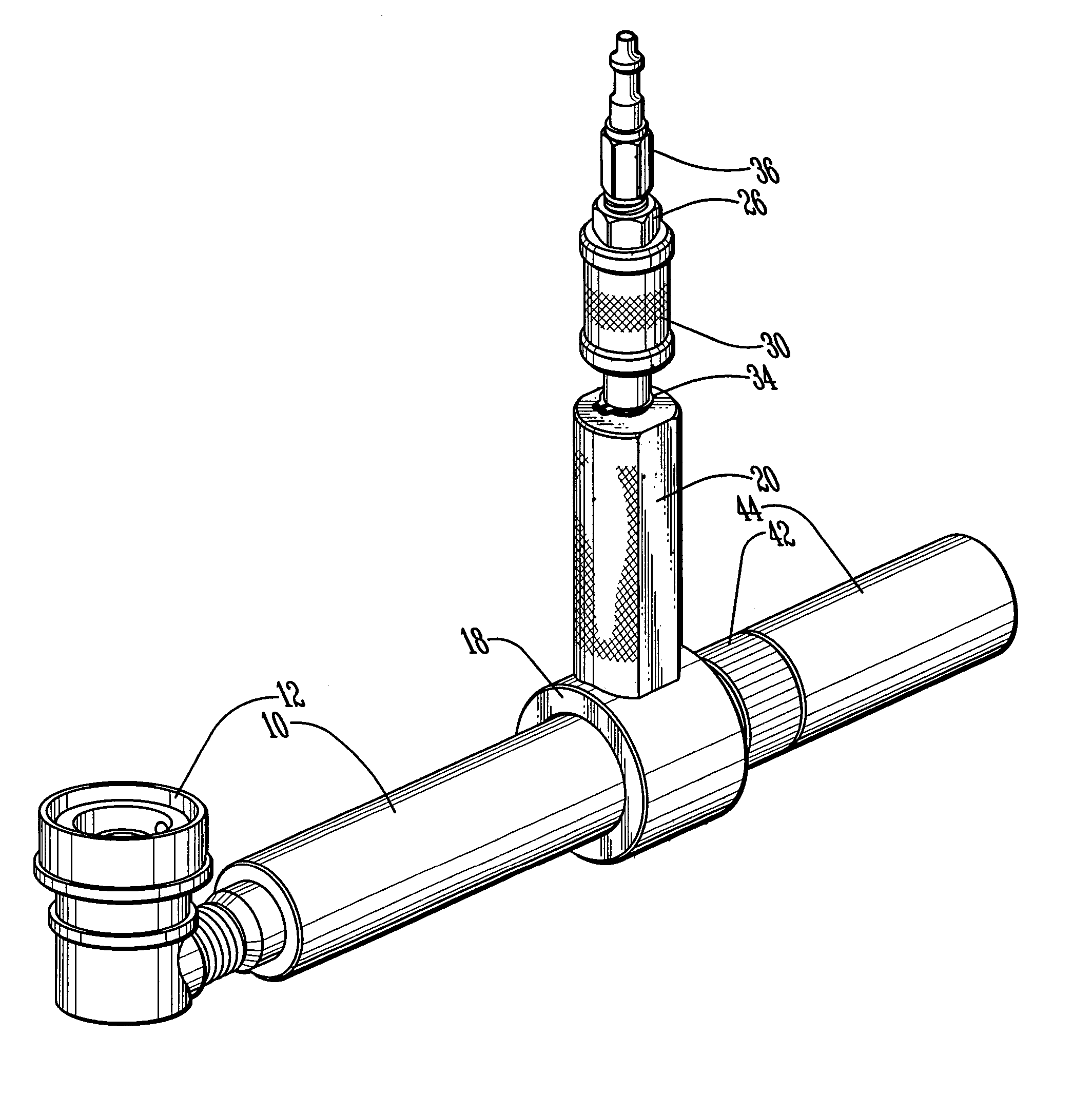
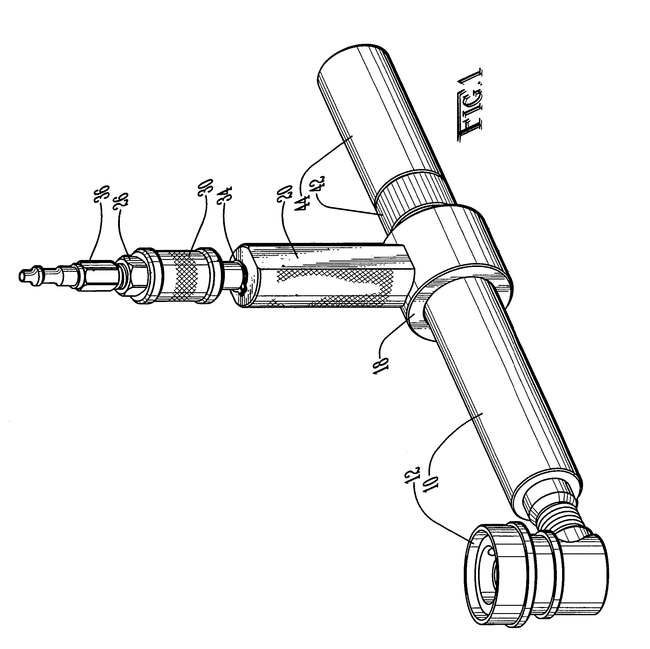
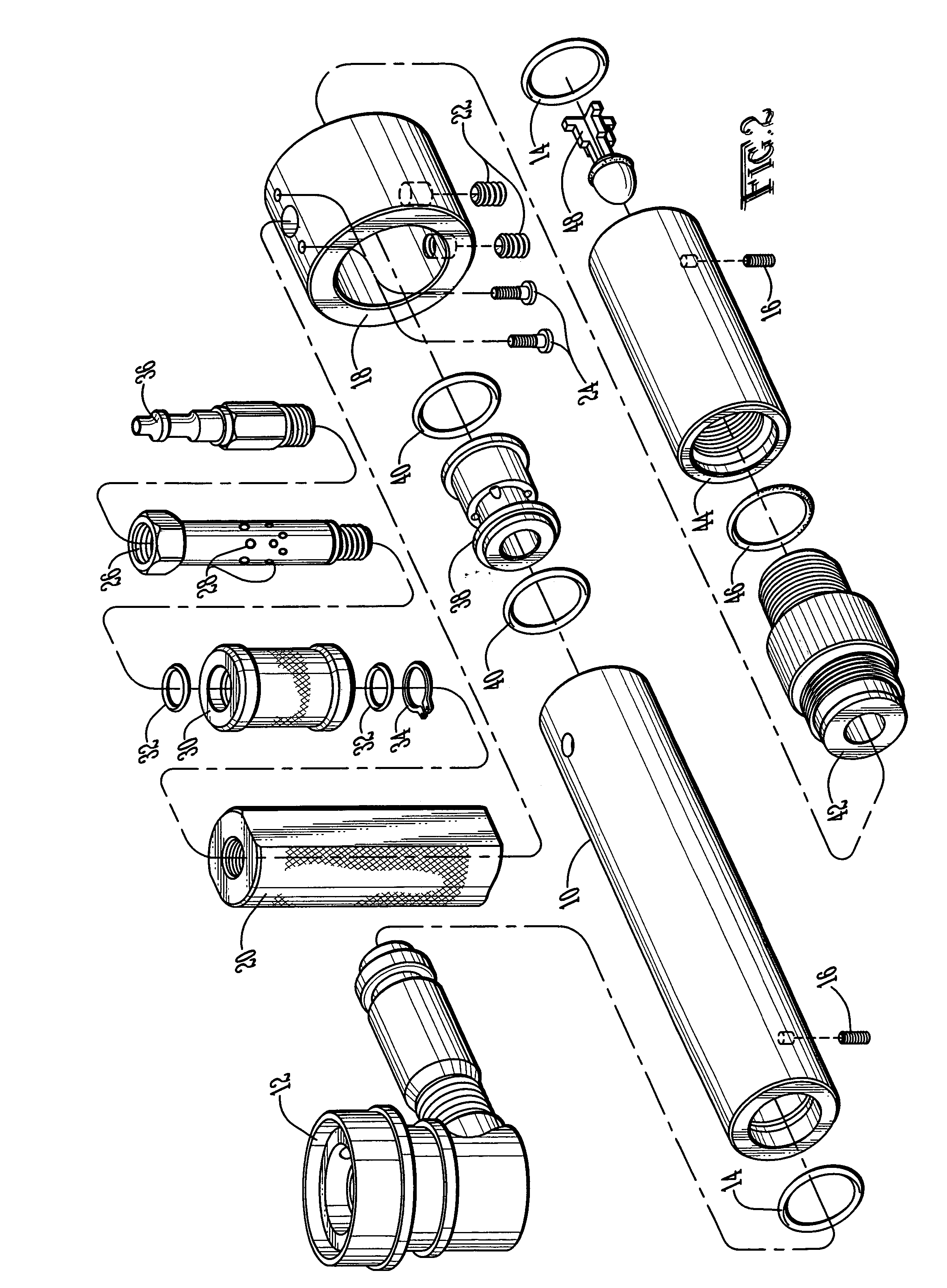
[0024]Referring to FIGS. 1 and 2, the major components of a preferred embodiment of the present invention may now be described. Inflation barrel 10 comprises a tube with an open bore. Removably attached to inflation barrel 10 in the “inflation” configuration, as depicted in FIGS. 1 and 2, is valve connector assembly 12. Valve connector assembly 12 is fashioned so as to provide a selectively lockable and unlockable engagement with a dunnage bag inflation valve (not shown). The valve connector assembly 12 may preferably be constructed as a ball-lock quick-disconnect valve connector as described in U.S. Pat. No. 5,437,301 to Ramsey, which is incorporated herein by reference. o-rings 14 is seated within an annular groove on the interior of inflation barrel 10, thereby providing an airtight seal between inflation barrel 10 and valve connector assembly 12. In the preferred embodiment, valve assembly 12 is held in place by set screw 16. Set screw 16 extends through a hole in the side of in...


PUM

PropertyMeasurementUnit
pressureaaaaaaaaaa
air pressureaaaaaaaaaa
timeaaaaaaaaaa

Abstract

A tool allowing both the inflation and deflation of air-filled bags such as dunnage bags is disclosed. The tool comprises a sliding control to easily and safely turn the flow of air on and off. The tool is switched from inflation to deflation mode by moving the bag connecting valve from one end of the device to the other.

Description

CROSS-REFERENCE TO RELATED APPLICATIONS[0001]This application is a continuation-in-part of U.S. utility patent application Ser. No. 10 / 817,356, filed on Apr. 2, 2004 now U.S. Pat No. 7,073,545, and entitled “Inflation and Deflation Apparatus,” which in turn claimed priority from U.S. provisional patent application no. 60 / 511,047, filed on Oct. 14, 2003, and entitled “Inflation and Deflation Apparatus.” Both of these applications are incorporated wherein by reference.BACKGROUND OF THE INVENTION[0002]The present invention relates to an apparatus for the inflation and deflation of air-filled bags, such as the dunnage bags commonly used to cushion cargo loads in truck trailers, railroad cars, and the like.[0003]Inflatable dunnage bags are a common means of cushioning loads shipped via truck trailer, railroad car, or other typical shipping container, particularly where the cargo only partially fills the container and shifting during transport might cause damage. Typical dunnage bags in u...

Claims


Application Information

Patent Timeline
Patent Type & Authority Patents(United States)
IPC IPC(8): B65B1/04B60P7/06
CPCB60P7/065Y10T137/3677Y10T137/3584
Inventor RAMSEY, J. WILLIAMSMITH, MIKE L.HOBBS, JAMES C.
Owner PREMARK PACKAGING LLC
Why Eureka
Try Eureka