Backrest for seats and chairs having pressure and tensile elements

a backrest and seat technology, applied in the field of seats and chairs, can solve the problems of spinal column deformation and the geometry of the supporting structure, and achieve the effect of preventing lateral bending of the seat back

Inactive Publication Date: 2008-01-22
EYSING VOLKER WILHELM +1
View PDF18 Cites 70 Cited by
  • Summary
  • Abstract
  • Description
  • Claims
  • Application Information

AI Technical Summary

Benefits of technology

[0006]Such chair-backs have the advantage that the backrest matches the shape of the spinal column with concave deformation and supports the latter at each point to an equal extent. The adjustment in the concave region of the backrest happens due to the shape of the supported back and the forces exerted on the backrest by the latter. A disadvantage of these chair-backs however is that the convex deformation in the lumbar region forcibly results from the geometry of the supporting structure and the deformation in the spinal column region.
[0016]The stiffness of the connection between the tension element and the pressure element affects the behaviour of the structure. Increased stiffness of the connection prevents displacement of the pressure element relative to the tension element at this junction point. The stiffness of the connection can be variously influenced. Expediently the tension element and the pressure element are connected to one another more stiffly in the region of the bearing axis and less stiffly between the end regions and the bearing axis.
[0046]In this case it is advantageous that as the result of a plastic profile with a plurality of horizontal chambers resilience can be achieved by the flexible chamber sidewalls and rigid lamellar bars between the chambers, which in particular allows the seat-back to be deformed to the front and rear around neutral axes at the lamella edges, in the case of backrests around horizontal neutral axes.
[0048]It is also proposed to prevent lateral bending of the seat-back if the load is not centric by additional pressure elements in the chambers. The seat-back can only mould itself as a whole to the spinal column and / or assume the shape of the back. Thus at the same time too soft a seat-back, in particular a dip in the centre, is avoided.

Problems solved by technology

A disadvantage of these chair-backs however is that the convex deformation in the lumbar region forcibly results from the geometry of the supporting structure and the deformation in the spinal column region.

Method used


Image

  • Backrest for seats and chairs having pressure and tensile elements
  • Backrest for seats and chairs having pressure and tensile elements
  • Backrest for seats and chairs having pressure and tensile elements

Examples


Embodiment Construction

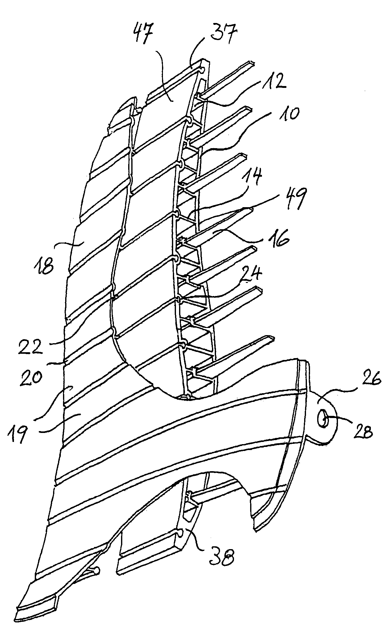
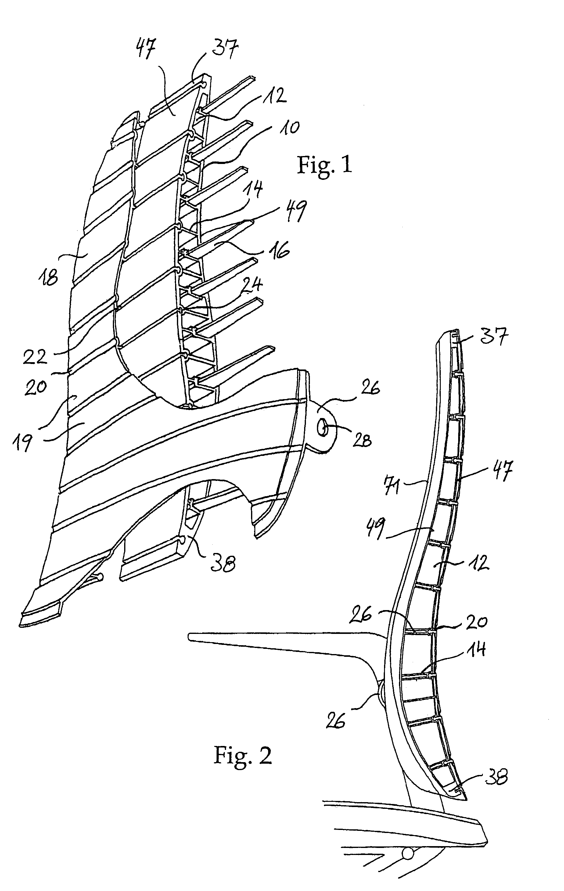
[0100]The plastic profile 10 illustrated in FIG. 1 exhibits a plurality of individual chambers 12, whereby lamellar bars 14 are formed between these chambers and in some of the bars (in FIG. 1 in every second bar) further slots are provided for receiving reinforcing strip-shaped elements 16, which protect the plastic profile against deformation around a vertical axis.

[0101]A rear reinforcement 18 is formed through second plastic lamellas 19 arranged individually on top of one another, vertically aligned and extending horizontally, which by means of PVC rubber sections 20 located in-between do not offer any resistance to the body-related deformation of the seat-back around horizontally tilting axes.

[0102]Instead of the plastic lamellas proposed a continuous lamella shell could also be used as an alternative.

[0103]The rubber sections 20 of each lamella 19 in a preferred embodiment exhibit rubber tongues 22, which engage in corresponding slots 24 of the plastic profile 10. Mounting ton...


PUM


Abstract

The invention relates to a backrest with a support area (71), at least one structure connected to the support area (71) or forming the support area (71), which structure (10) extends towards the top of the backrest from a first end region of the support area (71) to a second end region of the support area (71) and at the front has a tension element (49) and at the rear a pressure element (47). The tension element (49) connects the first end region (37) of the support area (71) to the second end region (38) of the support area (71) transmitting tensile forces. The pressure element (47) connects the first end region (37) of the support area (71) to the second end region (38) of the support area (71) transmitting thrust forces. Pressure element (47) and tension element (49) are in the extension direction non-displaceably connected to one another in the first and in the second end region of the support area (71). The tension element (49) and the pressure element (47) between the end regions (37, 38) are connected to one another in the extension direction displaceably against each other by means of the spacers (14) keeping the distance. The backrest has at least one bearing axis (43), with which it can be joined or is joined to a seat-back bracket at a distance from the first and from the second end region of the support area (71) between these end regions (37, 38).

Description

FIELD OF THE INVENTION[0001]The invention relates to a rest, for example a backrest for vehicle seats, that is to say car-, truck-, train- and aircraft-seats or a rest of a chair, in particular an office chair.BACKGROUND OF THE INVENTION[0002]A wide variety of backrests are known. Most are inherently rigid. A hard shell is provided only with upholstered padding on the seat side.[0003]Ergonomic seating however requires flexible resilience corresponding to the body shape supported by the supporting element in each case. In particular due to the different sizes and seat positions flexible resilience corresponding to the back shape supported by the seat-back as well as permanent support of the pelvis boundary is required in order to prevent the pelvis from tilting to the rear.[0004]The unclear text of the published EP-A-1040999, which is based on the similarly unclear application DE-A-19916 411, discloses a component for the absorption of forces, which component in the linear direction ...

Claims


Application Information

Patent Timeline
Patent Type & Authority Patents(United States)
IPC IPC(8): A47C7/02A47C7/46
CPCA47C7/46A47C7/467B60N2/4415B60N2/643B60N2/66A47C7/448B60N2/667B60N2/665B60N2/914
Inventor EYSING, VOLKER WILHELM
Owner EYSING VOLKER WILHELM
Why Eureka
Try Eureka