Communications jacks with compensation for differential to differential and differential to common mode crosstalk

a technology of communication connectors and differentials, applied in the direction of coupling devices, two-part coupling devices, electrical equipment, etc., can solve the problems of increasing the cost of the system, undesirable signals, and the susceptibleness of each wire in a pair of wires to pick up electrical noise, so as to improve the differential to common mode and the effect of differential to differential

Active Publication Date: 2008-01-22
COMMSCOPE INC
View PDF83 Cites 34 Cited by
  • Summary
  • Abstract
  • Description
  • Claims
  • Application Information

AI Technical Summary

Problems solved by technology

Each wire in a wire-pair is susceptible to picking up electrical noise from sources such as lightning, automobile spark plugs and radio stations to name but a few.
Of greater concern, however, is the electrical noise that is picked up from nearby wires or pairs of wires that may extend in the same general direction for some distances and not cancel differentially on the victim pair.
In all of the above situations, undesirable signals are present on the electrical conductors that can interfere with the information signal.
However, a problem case may be “pair 3” of one channel crosstalking to “pair 3” of another channel, even if the pair 3 plug and jack wires in each channel are remote from each other and the only coupling occurs between the routed cabling.
However, the inclusion of shields can increase cost of the system.
However, this is typically impractical because bundling of cables and patch cords is common practice due to “real estate” constraints and ease of wire management.
In spite of recent strides made in improving mated connector (i.e., plug jack) performance, and in particular reducing crosstalk at elevated frequencies (e.g., 500 MHz—see U.S. patent application Ser. No. 10 / 845,104, entitled NEXT High Frequency Improvement by Using Frequency Dependent Effective Capacitance, filed May 4, 2004, the disclosure of which is hereby incorporated herein by reference), channels utilizing connectors that rely on either these teachings or those of the '358 patent can still exhibit unacceptably high alien NEXT, particularly at very high frequencies (e.g., 500 MHz).

Method used


Image

  • Communications jacks with compensation for differential to differential and differential to common mode crosstalk
  • Communications jacks with compensation for differential to differential and differential to common mode crosstalk
  • Communications jacks with compensation for differential to differential and differential to common mode crosstalk

Examples


example

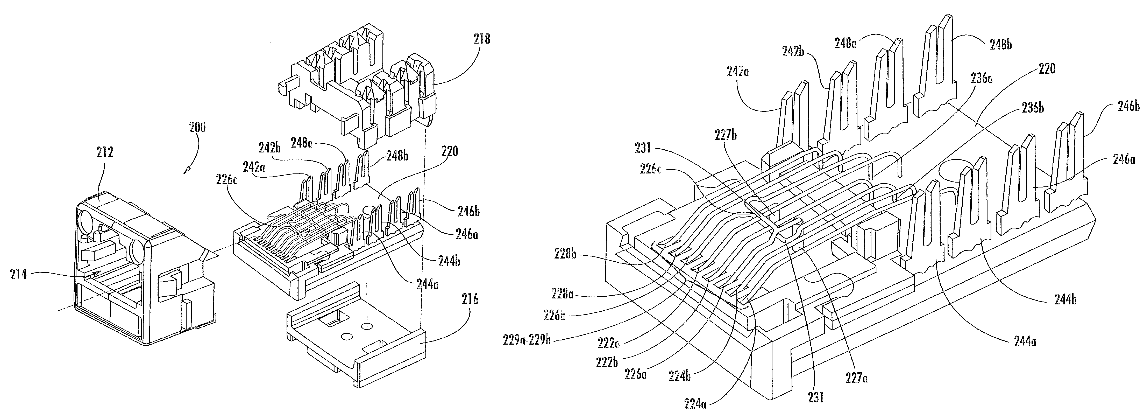
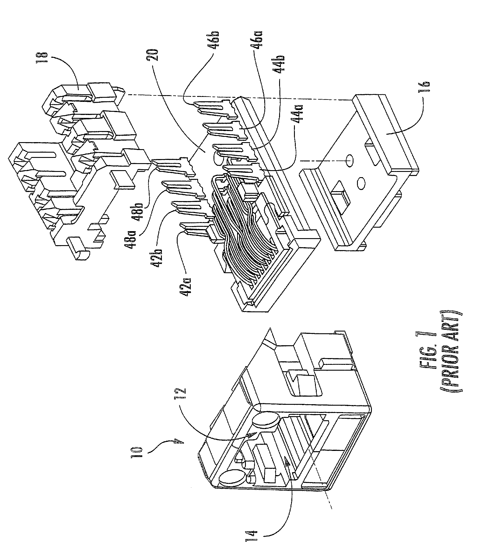
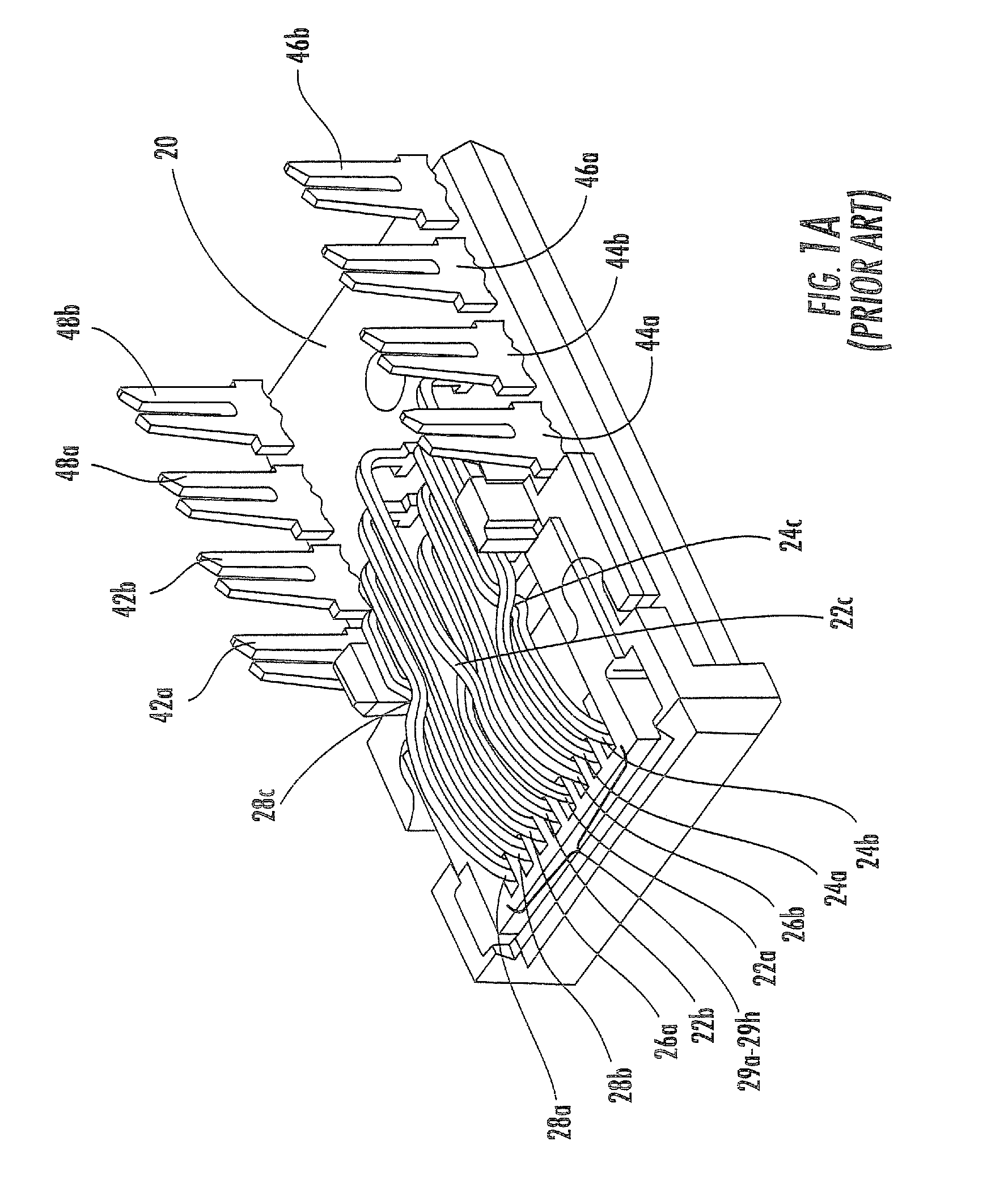
[0057]Communication jacks of the configuration illustrated in FIG. 1, mated with conventional plugs, were modeled and solved using finite element electromagnetic field simulation software. In one jack model designated “experimental jack”, the contact wire crossover configuration substantially matched the embodiment of the current invention illustrated in FIGS. 5-7A. In a second jack model, designated “prior art jack”, the contact wire crossover configuration substantially matched the prior art jack illustrated in FIGS. 1-3. The jack models were then solved for differential to common mode NEXT and FEXT crosstalk.

[0058]Differential to Common Mode Results for the problematic 3-2 and 3-4 pair combinations, where pair 3 is the differentially excited pair, are shown in FIGS. 8A-8D and FIGS. 9A-9D. For each of these pair combinations results are provided for forward NEXT, forward FEXT, reverse FEXT and reverse NEXT, wherein the term “forward” represents the testing orientation in which the...


PUM


Abstract

A communications jack assembly includes: a jack frame having a plug aperture; a dielectric mounting substrate attached to the jack frame; and a plurality of conductors engaged with the mounting substrate, each of the conductors including a fixed end portion mounted with the mounting substrate and a free end portion extending into the plug aperture for electrical contact with a mating plug, each of the free end portions having substantially the same profile and being substantially transversely aligned in side-by-side relationship. A first pair of conductors is sandwiched inside a second pair of conductors. The second pair of conductors includes a crossover, the positioning of crossover being selected to provide differential to common mode crosstalk compensation.

Description

CLAIM OF PRIORITY[0001]This application claims priority as a continuation-in-part application to U.S. patent application Ser. No. 11 / 088,044, filed Mar. 23, 2005 now U.S. Pat. No. 7,204,722, which in turn claims priority from U.S. Provisional Patent Application Ser. No. 60 / 636,595, filed Dec. 16, 2004, the disclosures of both of which are hereby incorporated herein in their entirety.FIELD OF THE INVENTION[0002]The present invention relates generally to communication connectors and more particularly to crosstalk compensation in communication connectors.BACKGROUND OF THE INVENTION[0003]In an electrical communication system, it is sometimes advantageous to transmit information signals (video, audio, data) over a pair of wires (hereinafter “wire-pair” or “differential pair”) rather than a single wire, wherein the transmitted signal comprises the voltage difference between the wires without regard to the absolute voltages present. Each wire in a wire-pair is susceptible to picking up ele...

Claims


Application Information

Patent Timeline
Patent Type & Authority Patents(United States)
IPC IPC(8): H01R24/00
CPCH01R13/6469Y10S439/941H01R24/64
Inventor HASHIM, AMIDGOODRICH, ROBERT RAY
Owner COMMSCOPE INC
Why Eureka
Try Eureka