Key sheet and manufacturing method for key sheet

a manufacturing method and key technology, applied in the field of key sheets, can solve the problems of key tops coming off, key tops not being manufactured by modifying, and the improved version of key sheets cannot be manufactured by modifying, so as to achieve the effect of easy control of the degree of spread of adhesive layers

Inactive Publication Date: 2008-01-22
SEKISUI POLYMATECH CO LTD
View PDF11 Cites 78 Cited by
  • Summary
  • Abstract
  • Description
  • Claims
  • Application Information

AI Technical Summary

Benefits of technology

[0011]The further object of the present invention is to obtain a manufacturing method for a key sheet that can adhere predetermined parts of key tops or the like to be fixed to the base sheet, precisely and surely.
[0051]According to the key sheet of the present invention, the key sheet can be caused to be a key sheet that has key tops and frame sheet on a base sheet made of a resin film. In addition, it is caused to be a thin key sheet where, in addition a problem such as the occurrence of distortion of the base sheet or the coming off of the key top hardly occurs, pushing operation of the key tops can be adequately performed, and a design in a housing of equipment such as a mobile-phone that exposes not only the key tops but also the frame sheet from an operating opening with no partitioning crosspiece, is realized.

Problems solved by technology

However, it was known that the improved version key sheet cannot be manufactured by modifying the structure of the conventional key sheets (11, 21), or by means of its manufacturing method.
It is the presence of the gaps that causes a problem of coming off of key tops.
Moreover, in the improved version key sheet where gaps between key tops are wider, and the frame is exposed, since the possibility for a nail to enter the gaps between the key tops and the base sheet becomes higher than that of the key sheet (21) where key tops (23) are arranged with narrower gaps, the coming off of the key tops causes larger problems.

Method used


Image

  • Key sheet and manufacturing method for key sheet
  • Key sheet and manufacturing method for key sheet
  • Key sheet and manufacturing method for key sheet

Examples


example 1 (

Samples 1 to 4)

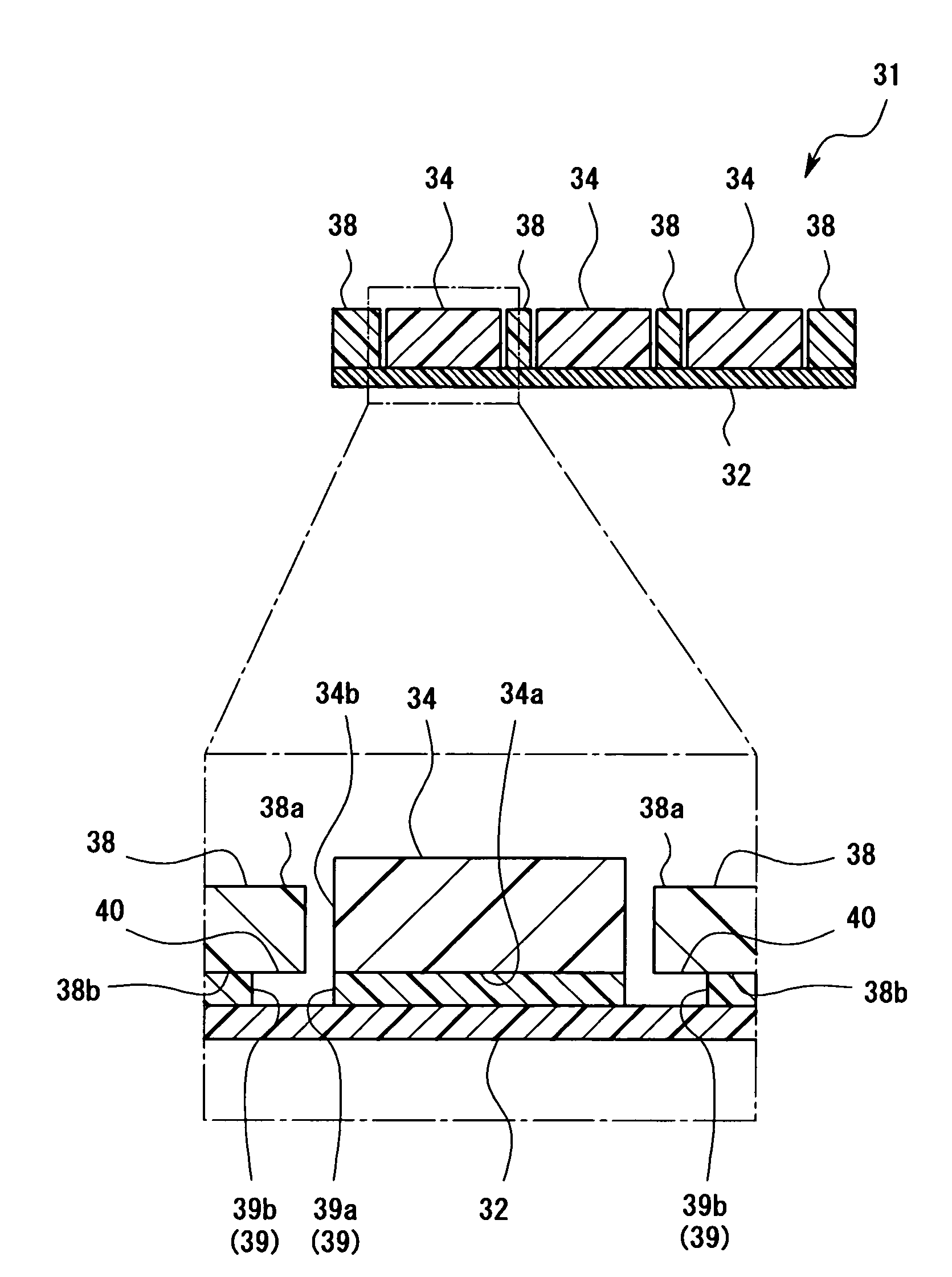
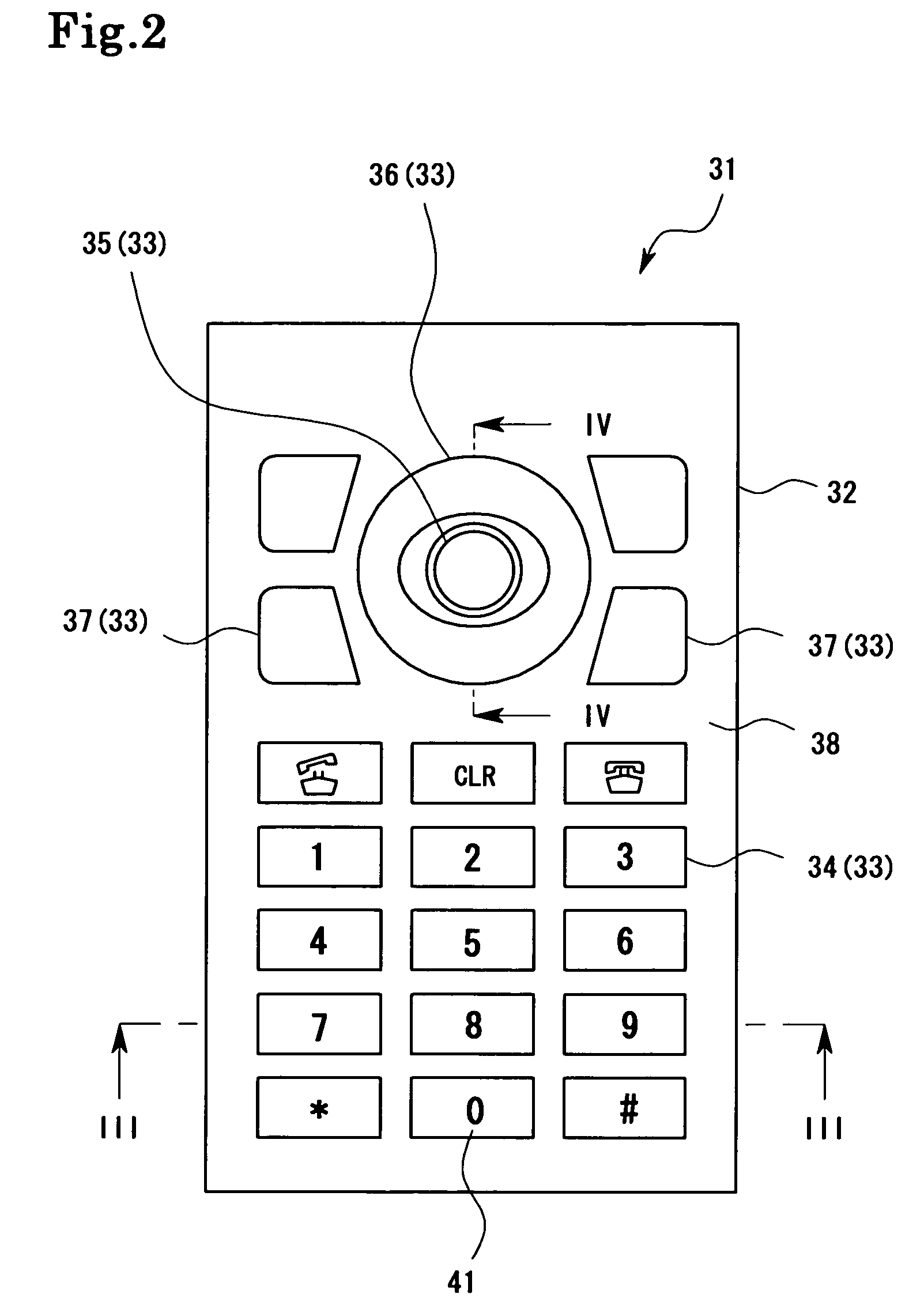
[0095]First, medium size key tops (34), a center key top (35), a ring key top (36), longitudinal key tops (37), were formed, respectively, using a polycarbonate resin, a frame sheet (38) was formed using a PET film with a thickness of 0.3 mm, and a base sheet (32) was formed using materials shown in the following Table 1. Next, using inks for printed adhesive layers (39) shown in Table 1, the printed adhesive layers (39) were formed on the bottom surfaces (33a) of each key tops (33) by means of screen printing. Here, on the entire bottom surfaces (34a, 35a) of the medium size key tops (34) and the center key top (35), the printed adhesive layers (39) were formed. Moreover, on the entire bottom surface (36b) of the ring key top (36), except for the part from the periphery to 0.5 mm inner from the periphery of the ring key top (36), of the outer edge (36a) at the side neighboring the center key top (35), the printed adhesive layer (39) was formed. Further, on the entire...

example 2 (

Samples 5 to 8)

[0099]Although, in example 1, the printed adhesive layer (39) was provided on a part of the bottom surface of the ring key tops (36) and the frame sheet (38), here, instead, the printed adhesive layer (39) was printed on the entire bottom surface of the ring key top (36) and the frame sheet (38). After that, the inks shown in Table 1 were printed on the parts on which an ink for the printed adhesive layer (39) was not coated, that are the parts from a predetermined periphery of each key tops (36) and each frame sheet (38) to parts inner from the predetermined periphery, to form masking layers (42). Conditions other than above were set to similar to those of example 1, and key sheets (31) indicated by samples 5 to 8 were obtained.

[0100]

TABLE 2Adhesive LayerBase Sheet(Key Top Side)Masking LayerTypeTypeTypeMethod of PressureThicknessThicknessThicknessBondingSample 5Base Sheet A#1Adhesive Layer AMasking Layer AEntire Bottom SurfacePETThermoplastic InkUV Inkof the Base She...

example 3 (

Samples 9 to 16)

[0102]Although, in examples 1 and 2, the entire bottom surface of the base sheet (32) was heated and pressed from the side of the base sheet (32), by a thermo-compression machine, here, instead, only parts corresponding to the parts on which the printed adhesive layers (39) were provided in example 1, were heated and pressed. In this manner, key sheets (31) indicated by samples 9 to 19 respectively using the same raw materials and configurations as those of samples 1 to 8 of examples 1 and 2, were produced.

[0103]

TABLE 3Adhesive LayerMaskingBase Sheet(Key Top Side)LayerMethodTypeTypeTypeof PressureThicknessThicknessThicknessBondingSample 9Base SheetAdhesive Layer ANoneEntire BottomA#1 PETThermoplastic InkSurface of the12 μm5 μmBase Sheetwas pressurebondedSample 10Base Sheet BAdhesive Layer BNoneSame as aboveNylonThermoplastic Ink30 μm3 μmSample 11Base Sheet CAdhesive Layer CNoneSame as aboveUrethaneThermoplastic Ink50 μm10 μmSample 12Base SheetAdhesive Layer DNoneSame...


PUM

PropertyMeasurementUnit
thicknessesaaaaaaaaaa
thicknessaaaaaaaaaa

Abstract

As a key sheet for fixing a base sheet and key tops to be arranged on the base sheet using adhesive layers, a key sheet where the key tops and the base sheet are fixed, is obtained by forming printed adhesive layers of the key tops on facing surfaces of at least either of the key tops or the base sheet by means of printing, and then bringing the printed adhesive layer into contact with the other facing surfaces in a softened or molten state, and by curing the printed adhesive layer.

Description

BACKGROUND OF THE INVENTION[0001]1. Field of the Invention[0002]The present invention relates to a key sheet used for an operating part of various kinds of equipment such as a mobile-phone, a PDA, a car navigation system, and a car audio system, and a manufacturing method thereof.[0003]2. Description of the Related Art[0004]In a mobile-phone (1) shown in FIG. 15, a key sheet (11) shown in FIG. 16 is used. The key sheet (11) is a base sheet (12) made of silicone gum on which a plurality of, total 21 pieces of, key tops (13) made of a hard resin is fixed by dropping an UV adhesive or the like. When a key top (13) is pushed, the base sheet (12) is bend, thereby a contact electrode on a circuit board (not shown) located on the bottom surface of the key sheet is pushed to be a state of switch input, and when pushing is removed, the key top (13) is returned to its initial position by the restoring force of the base sheet (12), and the state of switch input is released.[0005]Meanwhile, rec...

Claims


Application Information

Patent Timeline
Patent Type & Authority Patents(United States)
IPC IPC(8): H01H13/70
CPCH01H13/705H01H13/88Y10T428/24339Y10T29/49105H01H2229/00H01H13/704H01H9/18B29C65/4845H01H2221/058
Inventor NAKANISHI, YUTAKAMACHIDA, DAISUKEARAKI, WATARU
Owner SEKISUI POLYMATECH CO LTD
Why Eureka
Try Eureka