Ball measuring apparatus

a technology for measuring apparatus and balls, which is applied in the direction of measuring devices, golf accessories, instruments, etc., can solve the problems that the trajectory and flight distance of balls cannot be measured with high precision by simply using millimeter wave radars, and achieve the effect of suppressing the influence of weather and brightness, and high precision

Inactive Publication Date: 2008-01-22
DUNLOP SPORTS CO LTD
View PDF23 Cites 73 Cited by
  • Summary
  • Abstract
  • Description
  • Claims
  • Application Information

AI Technical Summary

Benefits of technology

[0013]The ball measuring apparatus can measure a trajectory and a flight distance with high precision while suppressing the influence of a weather and a brightness.

Problems solved by technology

However, it has been found that the trajectory and flight distance of the ball cannot be measured with high precision by simply using the millimeter wave radar.

Method used


Image

  • Ball measuring apparatus
  • Ball measuring apparatus
  • Ball measuring apparatus

Examples


first embodiment

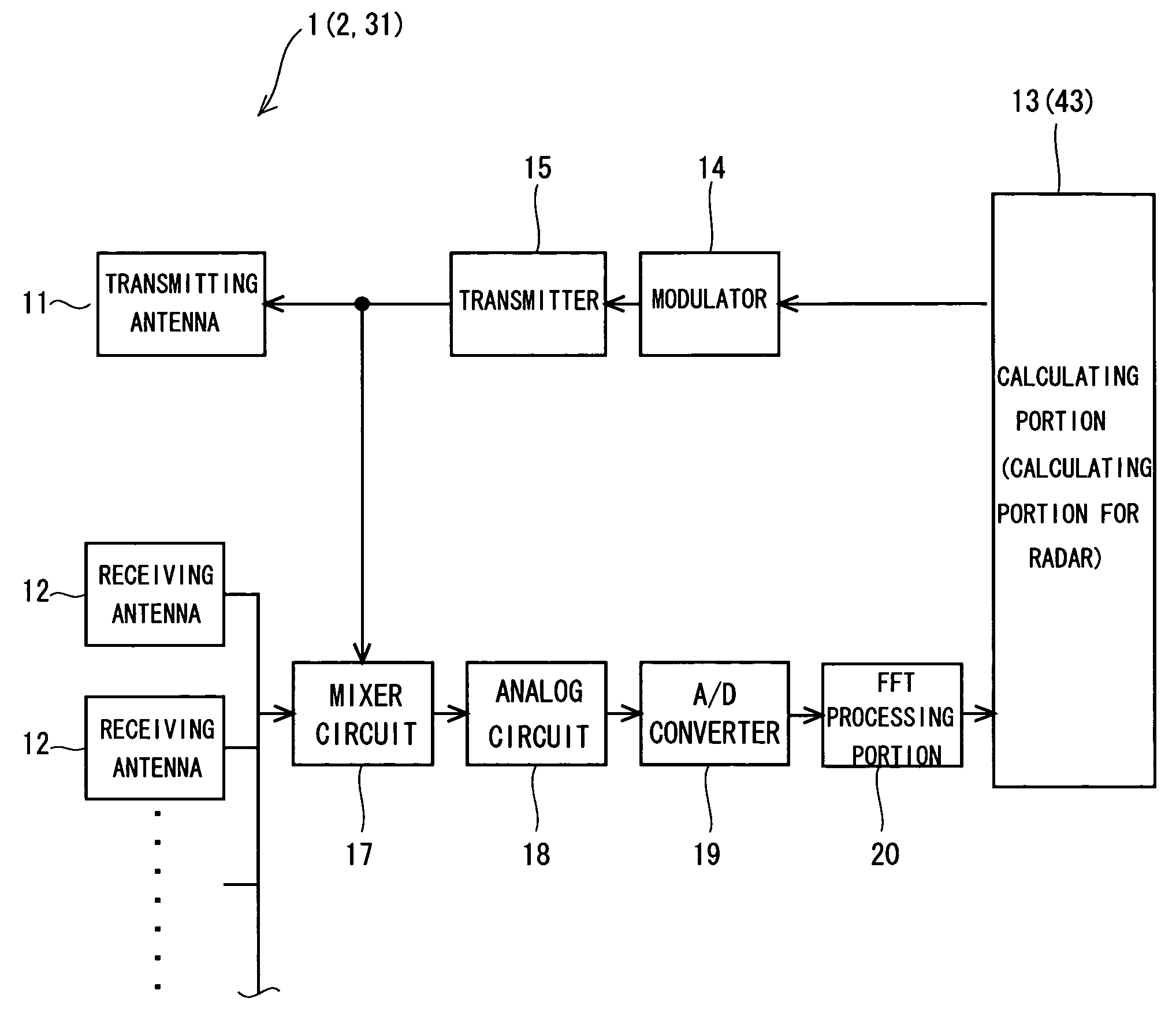
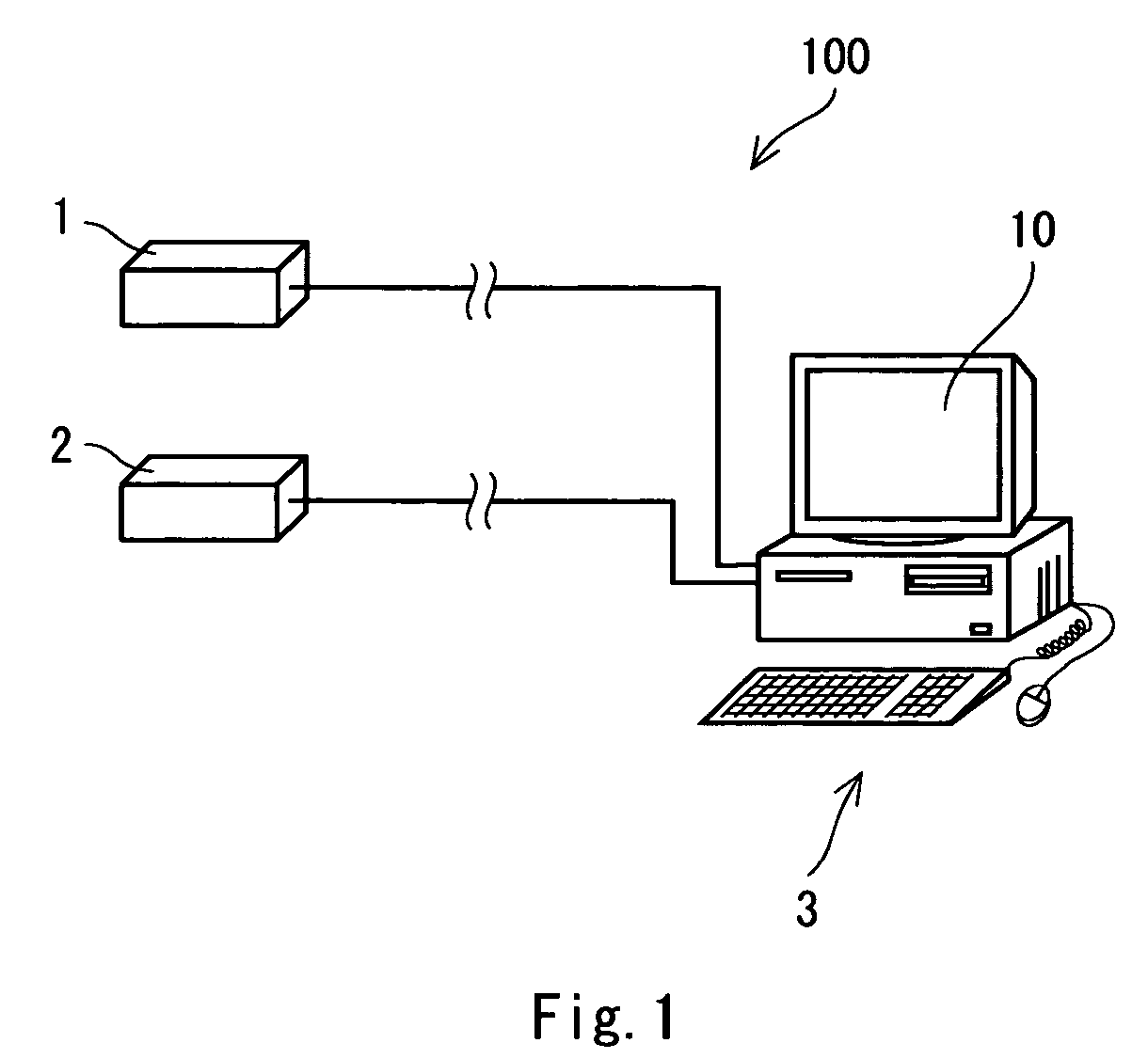
[0024]As shown in FIG. 1, a ball measuring apparatus 100 according to the present invention comprises a first millimeter wave radar device 1, a second millimeter wave radar device 2 and a computer portion 3. The first millimeter wave radar device 1 and the second millimeter wave radar device 2 are directly connected to the computer portion 3, respectively.

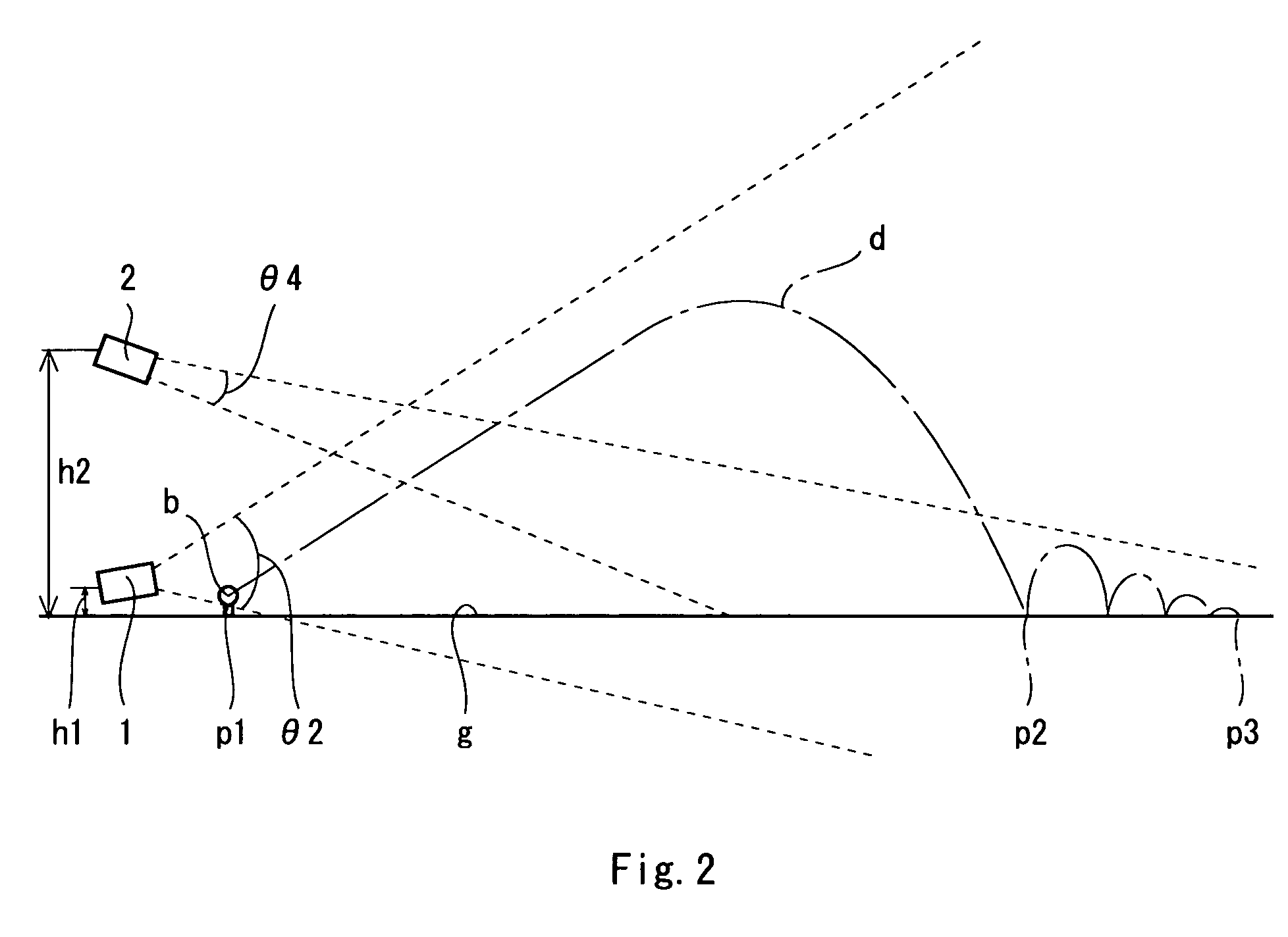
[0025]FIGS. 2 and 3 are views showing the relationship of an arrangement between a trajectory d of a golf ball b to be hit, and the radar device 1 and the radar device 2, FIG. 3 is a side view and FIG. 4 is a plan view seen from above. When the golf ball b put stationarily in a hitting position p1 is hit by a golf club which is not shown, it flies by describing the predetermined trajectory d. A starting point of the trajectory d is the hitting position p1 and an end point of the trajectory d is a landing position p2. The golf ball b landing in the landing position p2 rolls while bounding over a ground g, and stops at a stop positio...

second embodiment

[0053]FIG. 7 is a view showing a schematic structure of a ball measuring apparatus 101 according to the present invention. The ball measuring apparatus 101 comprises a millimeter wave radar device 31, a CCD camera 32, a computer portion 33, and a trigger portion 34. The millimeter wave radar device 31 is directly connected to the computer portion 33. The CCD camera 32 is coupled to the computer portion 33 through a cable compensator (not shown) if necessary.

[0054]FIGS. 8 and 9 are views showing the relationship of an arrangement between a trajectory d of a golf ball b to be hit, and the radar device 31 and the CCD camera 32, FIG. 8 is a side view and FIG. 9 is a plan view seen from above. When the golf ball b put stationarily in a hitting position p1 is hit by a golf club which is not shown, it flies by describing the predetermined trajectory d. The trajectory d is a track obtained during the flight of the ball b. A starting point of the trajectory d is the hitting position p1 and a...


PUM


Abstract

The present invention provides a ball measuring apparatus capable of measuring a trajectory of a ball from a hitting position to a landing position, the landing position and a stop position. A ball measuring apparatus 100 according to a first embodiment includes a first millimeter wave radar device 1 capable of carrying out a measurement from the hitting position to a predetermined position of the trajectory and having at least one transmitting antenna and a plurality of receiving antennas, and a second millimeter wave radar device 2 capable of measuring the stop position and having at least one transmitting antenna and a plurality of receiving antennas. A ball measuring apparatus 101 according to a second embodiment has a millimeter wave radar device 31 and a CCD camera 32.

Description

[0001]This application claims priority on Patent Application No. 2005-289771 filed in JAPAN on Oct. 3, 2005 and Patent Application No. 2005-290023 filed in JAPAN on Oct. 3, 2005, the entire contents of which are hereby incorporated by reference.BACKGROUND OF THE INVENTION[0002]1. Field of the Invention[0003]The present invention relates to an apparatus for measuring a trajectory and a flight distance of a ball and more particularly to a ball measuring apparatus which is suitable for measuring a trajectory and a flight distance of a golf ball.[0004]2. Description of the Related Art[0005]As an apparatus for measuring a trajectory of a golf ball, conventionally, an apparatus using a CCD camera has been proposed. Japanese Laid-Open Patent Publication No. 2001-145718 has disclosed an apparatus for measuring a trajectory of a ball using at least one CCD camera for detecting a maximum point and at least one CCD camera for detecting a drop point. Japanese Laid-Open Patent Publication No. 20...

Claims


Application Information

Patent Timeline
Patent Type & Authority Patents(United States)
IPC IPC(8): G01S13/42A63B69/36G01S13/00
CPCA63B24/0021A63B69/3658G01S13/42G01S13/58G01S13/87G01S13/867A63B2024/0031A63B2024/0034A63B2024/0037
Inventor SAJIMA, TAKAHIRO
Owner DUNLOP SPORTS CO LTD
Why Eureka
Try Eureka