
Arrangement and method for spatial visualization

a spatial visualization and arrangement technology, applied in the field of spatial visualization arrangement and method, can solve the problems of high cost of procurement and maintenance, poor suppression of the respective “wrongly” polarized light, and rise in the proportion of “wrongly” polarized light transmitted by both spectacle lenses, and achieve the effect of low cos

Inactive Publication Date: 2008-01-22
FRAUNHOFER GESELLSCHAFT ZUR FOERDERUNG DER ANGEWANDTEN FORSCHUNG EV
View PDF7 Cites 21 Cited by
  • Summary
  • Abstract
  • Description
  • Claims
  • Application Information

AI Technical Summary

Benefits of technology

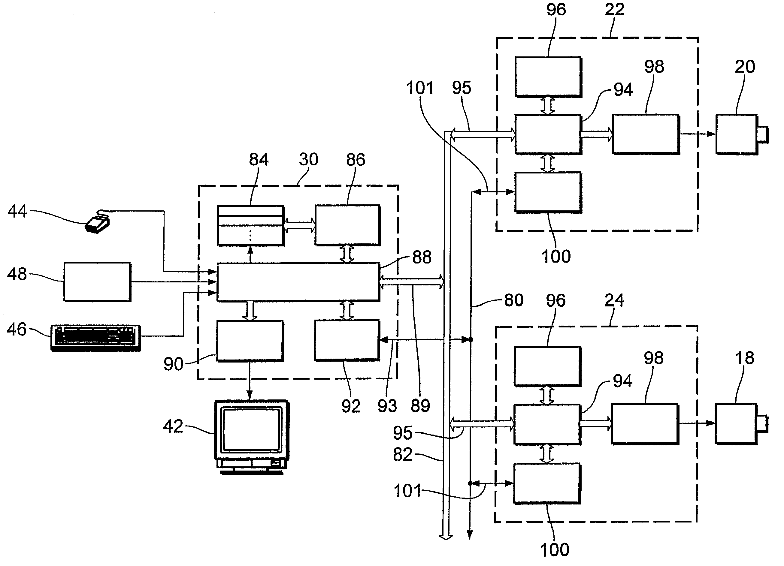
[0013]The object of the invention is to provide an apparatus for image data computation and for synchronous image data output, which can be produced at low cost.

Problems solved by technology

However, the proportion of “wrongly” polarized light which is transmitted by both spectacle lenses rises when the viewer inclines his head.
The disadvantage of that method is the poorer suppression of the respective “wrongly” polarized light.
The disadvantage of that system is that the computation and control system used is a highly developed expensive special item which is cost-intensive in terms of procurement and maintenance.

Method used


Image

  • Arrangement and method for spatial visualization
  • Arrangement and method for spatial visualization
  • Arrangement and method for spatial visualization

Examples


first embodiment

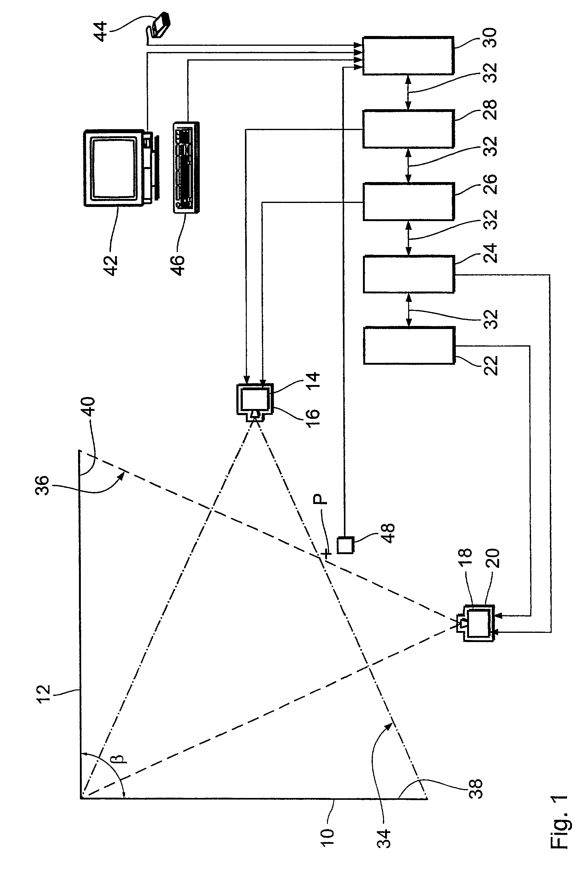
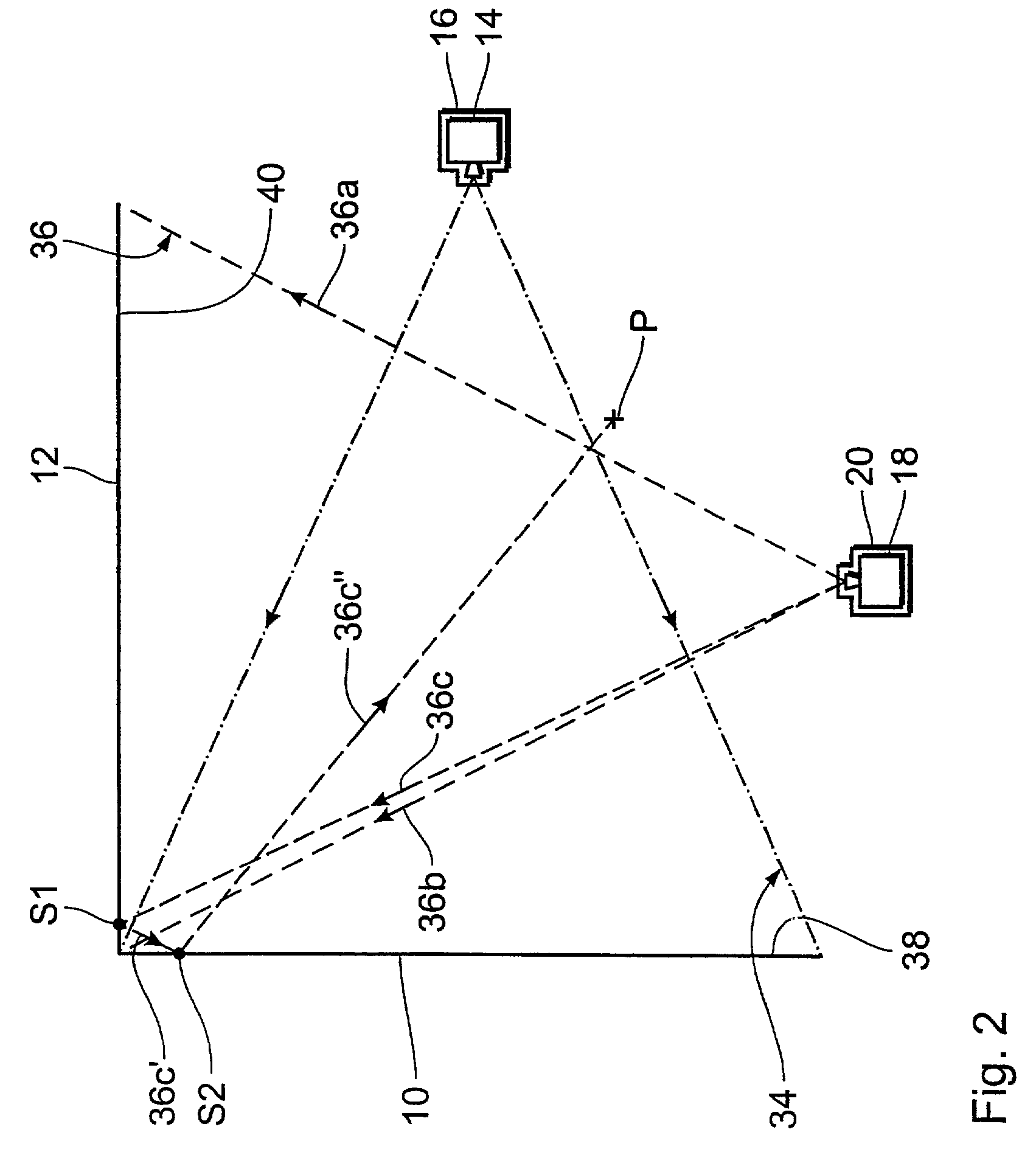
[0093]FIG. 1 shows a simplified plan view of an arrangement for spatial visualization. The arrangement is designed for stereo projection from the direction of the viewer (front projection). The stereo effect is produced passively and can be perceived by a pair of polarization filter spectacles.

[0094]This arrangement has two screens 10 and 12 which are set up at a right angle, four projectors 14 through 20 and a graphics computer system of 5 networked computers 22 through 30. The network connection between the computers 22 through 30 is indicated by the double-headed arrows 32.

[0095]The screens 10 and 12 (hereinafter also referred to as scattering walls) are set up at a right angle β and are in immediately adjoining relationship without gap. They can be fixedly or releasably connected together in the region of the angle β. Releasable erection of the screens has the advantage that the walls can be freshly positioned relative to each other as desired for experimentation purposes. Thus ...

second embodiment

[0193]FIG. 6 shows a simplified block circuit diagram of an apparatus for image data computation and synchronous image data output. The present embodiment is the same in large parts as the embodiment described with reference to FIG. 5. Therefore, in this case the same structural elements are denoted by the same references and hereinafter it is only the differences in relation to the apparatus of FIG. 5, that will be described.

[0194]The graphics clients 94 of the graphics computers 22 and 24 are connected on the output side to a partial image switching unit 102. The partial image switching unit has two image data intermediate memories 104 and 106. The first image data intermediate memory 104 is connected to the graphics client unit 94 of the graphics computer 22 and the second image data intermediate memory 106 is connected to the graphics client unit 94 of the graphics computer 24. The image data intermediate memories 104 and 106 receive the image data outputted by the associated gr...


PUM


Abstract

An apparatus for image data computation and for synchronous data output. An arrangement for producing and reproducing two partial light images which together can be perceived as a light image having a three-dimensional effect. A method of synchronous reproduction of time image sequences by at least two image reproduction devices. The apparatus according to an embodiment of the present invention has a master-client structure. A graphics master unit and at least two graphics clients are connected together by way of a first message channel and by way thereof exchange first messages, such that computation and projection of the partial images is synchronized.

Description

[0001]The invention concerns an apparatus for image data computation and for synchronous image data output. The invention further concerns a graphics master module, a graphics client module and an image switching module. The invention further concerns an arrangement for producing and simultaneously reproducing at least two partial light images which together can be perceived as a three-dimensionally acting light image, as well as an arrangement for producing and reproducing in succession in respect of time at least two partial light images which together can be perceived as a three-dimensionally acting light image. Finally the invention concerns a method of synchronously computing and outputting image data of at least two partial images of an image.BACKGROUND OF THE ART[0002]The representation of images which have a three-dimensional effect is based on the reproduction of two partial images on a picture screen using stereo projection. A first partial image reproduces a scene in the ...

Claims


Application Information

Patent Timeline
IPC IPC(8): G06F15/16G06T17/00H04N13/363
CPCG06T17/00H04N13/0275H04N13/0434H04N13/0438H04N13/0459H04N13/0497H04N13/0059H04N13/0285H04N13/337H04N13/341H04N13/194H04N13/275H04N13/363H04N13/286H04N13/398
Inventor ISAKOVIC, KARSTENHAULSEN, IVOGROTH, BORIS
Owner FRAUNHOFER GESELLSCHAFT ZUR FOERDERUNG DER ANGEWANDTEN FORSCHUNG EV
Learn More