Packet transmission method, network element and arrangement

a packet transmission and network element technology, applied in data switching networks, frequency-division multiplexes, instruments, etc., can solve the problem of drastically achieve the effect of reducing the throughput of a packet connection, maximizing the throughput probability of high-priority packets, and reducing the number of packets

Active Publication Date: 2008-01-22
RPX CORP
View PDF6 Cites 0 Cited by
  • Summary
  • Abstract
  • Description
  • Claims
  • Application Information

AI Technical Summary

Benefits of technology

[0007]The invention provides a packet transmission solution where the quality of service may be improved. According to an embodiment of the invention, there is provided a packet transmission method in a telecommunication network. The method includes: transmitting, in the network, packets of different priority on at least some connections; estimating a value for the quality of service required for sending high priority packets with a given successful decoding probability; and controlling the interference in the network such that the quality of service for each connection has at least the estimated value.
[0010]The method and system of the invention provide several advantages. According to one embodiment of the invention, packets are thus categorized in different priority classes. An example of a high priority packet is an acknowledgement packet. The loss of an acknowledgement (ACK) packet lowers the throughput of a packet connection drastically, as it leads to redundant retransmissions. Thus, even if the system has a connection based priority in use and the link layer throughput is therefore maximized, the application level throughput may still very well be sub-optimal, as there may be redundant retransmissions of large packets due to ACK packet losses. In the embodiments of the invention the throughput probability of high priority packets is larger and thus the quality of service (QoS) experienced by a user is higher.

Problems solved by technology

The loss of an acknowledgement (ACK) packet lowers the throughput of a packet connection drastically, as it leads to redundant retransmissions.
Thus, even if the system has a connection based priority in use and the link layer throughput is therefore maximized, the application level throughput may still very well be sub-optimal, as there may be redundant retransmissions of large packets due to ACK packet losses.

Method used


Image

  • Packet transmission method, network element and arrangement
  • Packet transmission method, network element and arrangement
  • Packet transmission method, network element and arrangement

Examples


Embodiment Construction

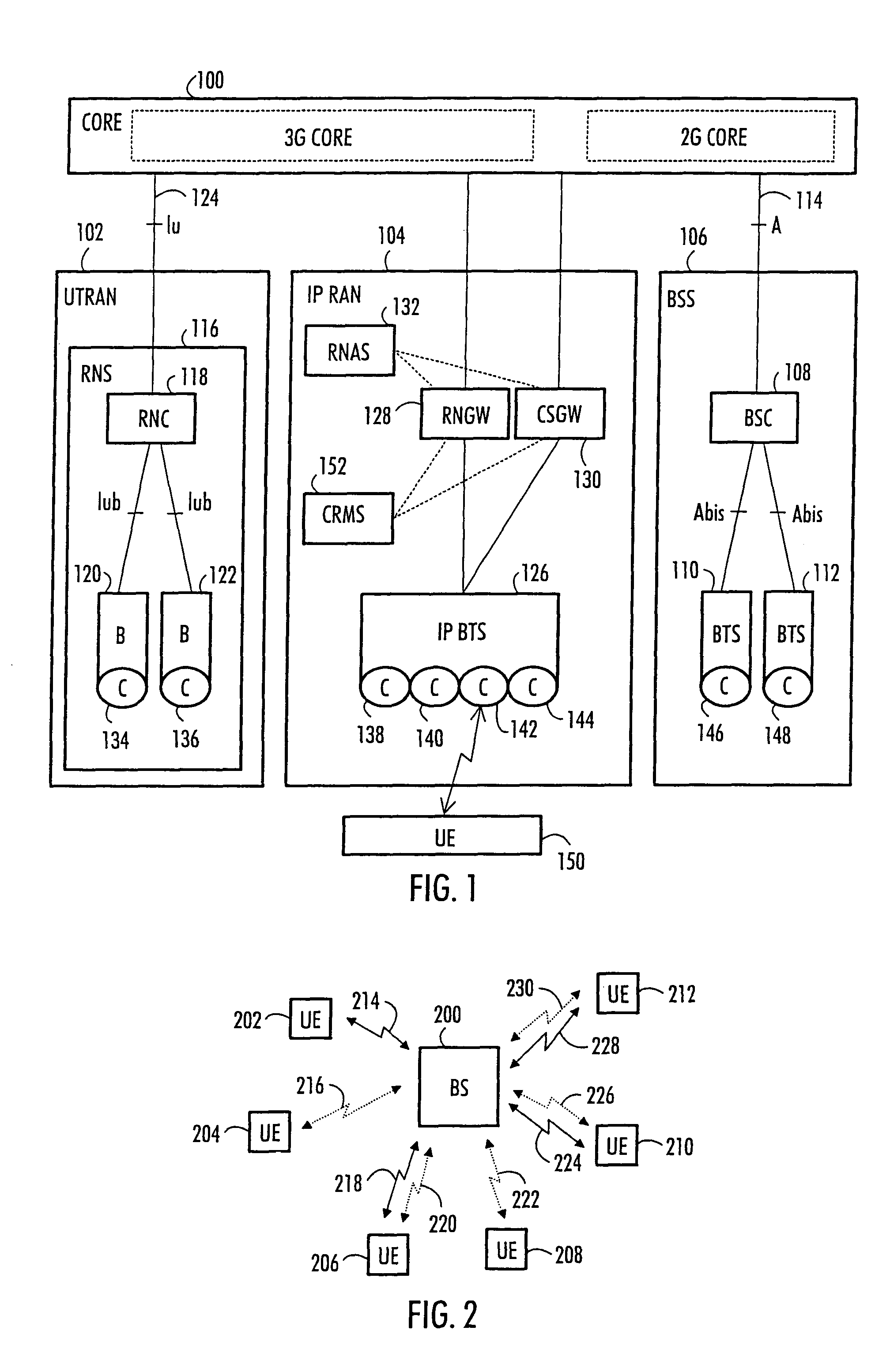
[0015]With reference to FIG. 1, an example of a data transmission network to which the embodiments of the invention can be applied is shown. FIG. 1 illustrates a simplified radio system, which comprises the main parts of a radio system: a core network (CN) 100, radio access networks 102, 104, 106 and user equipment (UE) 150. The described network is a mobile telecommunications network, but the invention is not limited to such a network, as is clear to one skilled in the art.

[0016]FIG. 1 shows the general architecture of an evolutionary Third Generation (3G) radio system using different technologies and interoperation of different generations of radio access networks, wherein network elements of different generations coexist. The radio system of a 2.5 generation radio system is represented by a radio system which is based on the GSM (Global System for Mobile Communications) and which uses the EDGE technique (Enhanced Data Rates for Global Evolution) for increasing the data transmissi...


PUM


Abstract

A packet transmission method in a telecommunication network is provided. According to one embodiment, the method includes the steps of transmitting, estimating and controlling. The transmitting step transmits, in the network, packets of different priority on at least some connections. The estimating step estimates a value for the quality of service required for sending high priority packets with a given successful decoding probability. The controlling step controls the interference in the network such that the quality of service for each connection has at least the estimated value.

Description

CROSS-REFERENCE TO RELATED APPLICATIONS[0001]This application claims priority of U.S. Provisional Patent Application Ser. No. 60 / 474,676 entitled “Packet Transmission Method, Network Element and Arrangement,” filed Jun. 2, 2003, the entire contents of which are incorporated herein by reference.BACKGROUND OF THE INVENTION[0002]1. Field of the Invention[0003]The invention relates to a packet transmission method and arrangement in telecommunication networks. Especially the invention relates to improving the quality of service in connections employing packet transmission.[0004]2. Description of the Related Art[0005]In telecommunication networks, the quality of a connection may vary from time to time. This applies especially to radio networks where the quality of service is affected by interference and varying propagation conditions. In systems employing packet transmission, poor quality of service has an effect on packet throughput. In poor conditions packets may be dropped or received ...

Claims


Application Information

Patent Timeline
Patent Type & Authority Patents(United States)
IPC IPC(8): H04J1/16H04J3/16H04L12/56
CPCH04L12/5695H04L47/745H04L47/805H04L47/822H04L47/824H04W72/1226H04L47/70H04W72/54
Inventor KAKANI, NAVEEN KUMARCLANTON, CHRISTOPHER
Owner RPX CORP
Why Eureka
Try Eureka