
Method and apparatus for data transfer using a time division multiple frequency scheme supplemented with polarity modulation

Inactive Publication Date: 2008-01-22
GENERAL ATOMICS
View PDF98 Cites 74 Cited by
  • Summary
  • Abstract
  • Description
  • Claims
  • Application Information

AI Technical Summary

Problems solved by technology

Unfortunately, present-day communications technologies fall short of providing the technical requirements necessary to support such demands.
However, such schemes may be more susceptible to increases in background noise level and to multipath interference.
Some narrowband schemes may also be more likely to interfere with other systems (e.g. due to a higher concentration of energy in the particular frequency band being used).
For example, some may provide low cost and low power consumption but only at low bit rate, while others may have higher bit rates but be unacceptable in terms of cost and / or rate of power consumption.

Method used


Image

  • Method and apparatus for data transfer using a time division multiple frequency scheme supplemented with polarity modulation
  • Method and apparatus for data transfer using a time division multiple frequency scheme supplemented with polarity modulation
  • Method and apparatus for data transfer using a time division multiple frequency scheme supplemented with polarity modulation

Examples


Embodiment Construction

[0109]In the description and claims that follow, certain terms may be defined as follows:

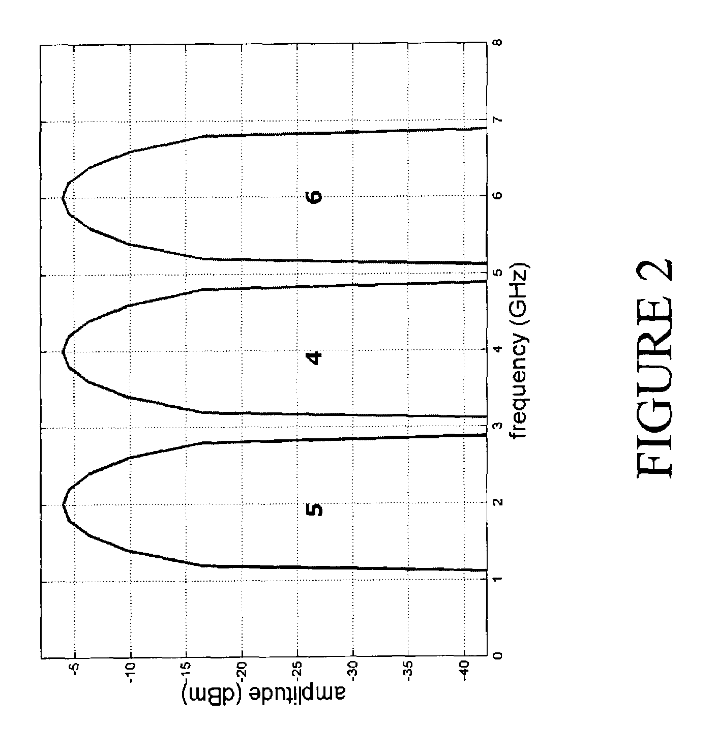
[0110]The term ‘frequency band’ denotes a portion of the frequency spectrum. The term ‘center frequency’ as applied to a frequency band denotes a frequency at the arithmetic mean of the frequencies of the boundaries of the frequency band. As defined herein, frequency bands may be adjacent to one another but are distinct from one another and do not overlap.

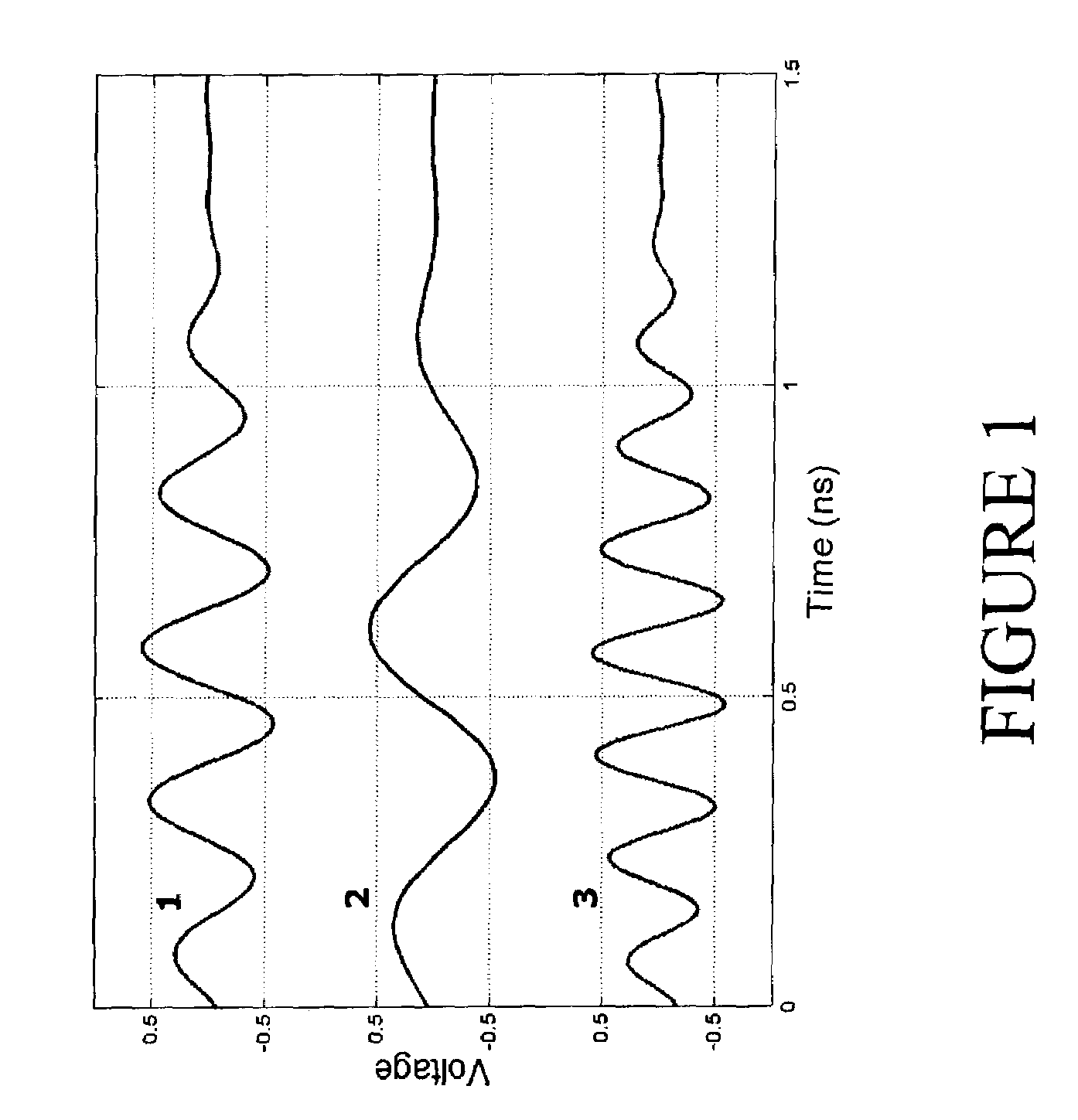
[0111]The term ‘burst’ denotes the emission of an amount of energy within a particular range of frequencies and over a limited period of time. A burst may include one or more cycles of a waveform (e.g. a sine wave). A burst may even be limited to less than one cycle of a waveform. In some applications, two or more bursts may be transmitted simultaneously. Beginning the transmission of a burst is also referred to as ‘triggering’ the burst. Transferring a burst from the generating circuitry (e.g. as described herein) to the transmission medium or...


PUM


Abstract

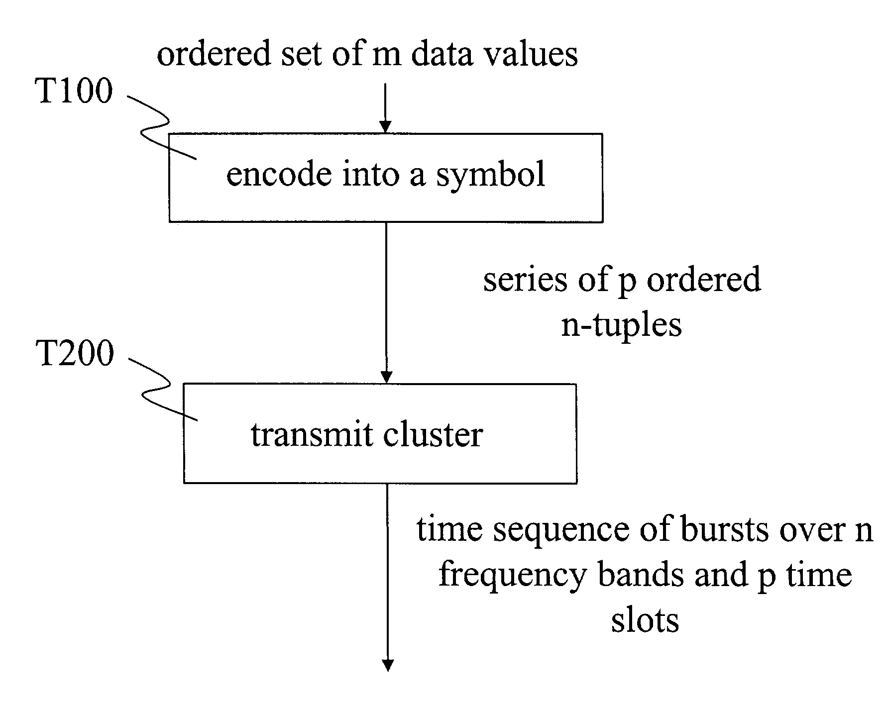
A method of data transmission according to one embodiment of the invention includes encoding a set of data values to produce a corresponding series of ordered n-tuples. The method also includes transmitting, according to the series of ordered n-tuples, a plurality of bursts over a plurality n of frequency bands. Specifically, for each of the plurality of bursts, a frequency band occupied by the burst is indicated by the order within its n-tuple of an element corresponding to the burst. A bandwidth of at least one of the plurality of bursts is at least two percent of the center frequency of the burst. Information is encoded into a polarity of at least one of the plurality of bursts.

Description

RELATED APPLICATIONS[0001]This application claims priority to U.S. Provisional Patent Applications No. 60 / 359,044 (“POLARITY SIGNALING METHODS BASED ON TDMF UWB WAVEFORMS,” filed Feb. 20, 2002); No. 60 / 359,045 (“CHANNELIZATION METHODS FOR TIME-DIVISION MULTIPLE FREQUENCY COMMUNICATION CHANNELS,” filed Feb. 20, 2002); No. 60 / 359,064 (“HYBRID SIGNALING METHODS BASED ON TDMF UWB WAVEFORMS,” filed Feb. 20, 2002); and No. 60 / 359,147 (“TRANSMITTER AND RECEIVER FOR A TIME-DIVISION MULTIPLE FREQUENCY COMMUNICATION SYSTEM,” filed Feb. 20, 2002); No. 60 / 359,094 (“PHY LEVEL ERROR DETECTION / CORRECTION FOR TDMF,” filed Feb. 20, 2002); No. 60 / 359,095 (“ADAPTING TDMF SIGNALING TO NARROWBAND INTERFERENCE SOURCES,” filed Feb. 20, 2002); and No. 60 / 359,046 (“METHOD OF DECODING TO EXPLOIT TDMF (FREQUENCY / TIME) CHARACTERISTICS,” filed Feb. 20, 2002); all of which applications are incorporated in their entirety herein by reference.[0002]This application is a continuation-in-part (CIP) of the following U...

Claims


Application Information

Patent Timeline
IPC IPC(8): H04J4/00H04B14/04H03K3/03H03K5/00H03K5/13H03K5/15H04B1/69H04L1/08H04L5/06H04L5/26H04L25/49H04L27/26H04L27/28
CPCH03K3/0315H03K5/133H03L7/0997H04B1/7176H04L1/08H04L5/003H04L5/06H04L5/26H04L25/4902H04L27/02H04L27/2602H04L27/28H03K5/1508H03K2005/00026H03K2005/00058H03K2005/00097H03K2005/00267H04L5/0005H04L5/006
Inventor ROGERSON, GERALD D.FURUNO, DAVID S.GEHRING, STEPHAN W.WALKER, MICHAEL L.AIELLO, ROBERTO
Owner GENERAL ATOMICS
Learn More