
Dual-mode clock for improved power management in a wireless device

Active Publication Date: 2008-01-22
AVAGO TECH INT SALES PTE LTD
View PDF6 Cites 15 Cited by
  • Summary
  • Abstract
  • Description
  • Claims
  • Application Information

AI Technical Summary

Benefits of technology

[0010]By switching between low-power mode and normal mode, the system is operable to provide a high quality clock signal for use by the RF analog module when it is operational

Problems solved by technology

However, the lack of a wired connection also requires that the wireless input devices contain their own power supply, i.e., that they be battery pow

Method used


Image

  • Dual-mode clock for improved power management in a wireless device
  • Dual-mode clock for improved power management in a wireless device
  • Dual-mode clock for improved power management in a wireless device

Examples


Example

DETAILED DESCRIPTION OF THE DRAWINGS

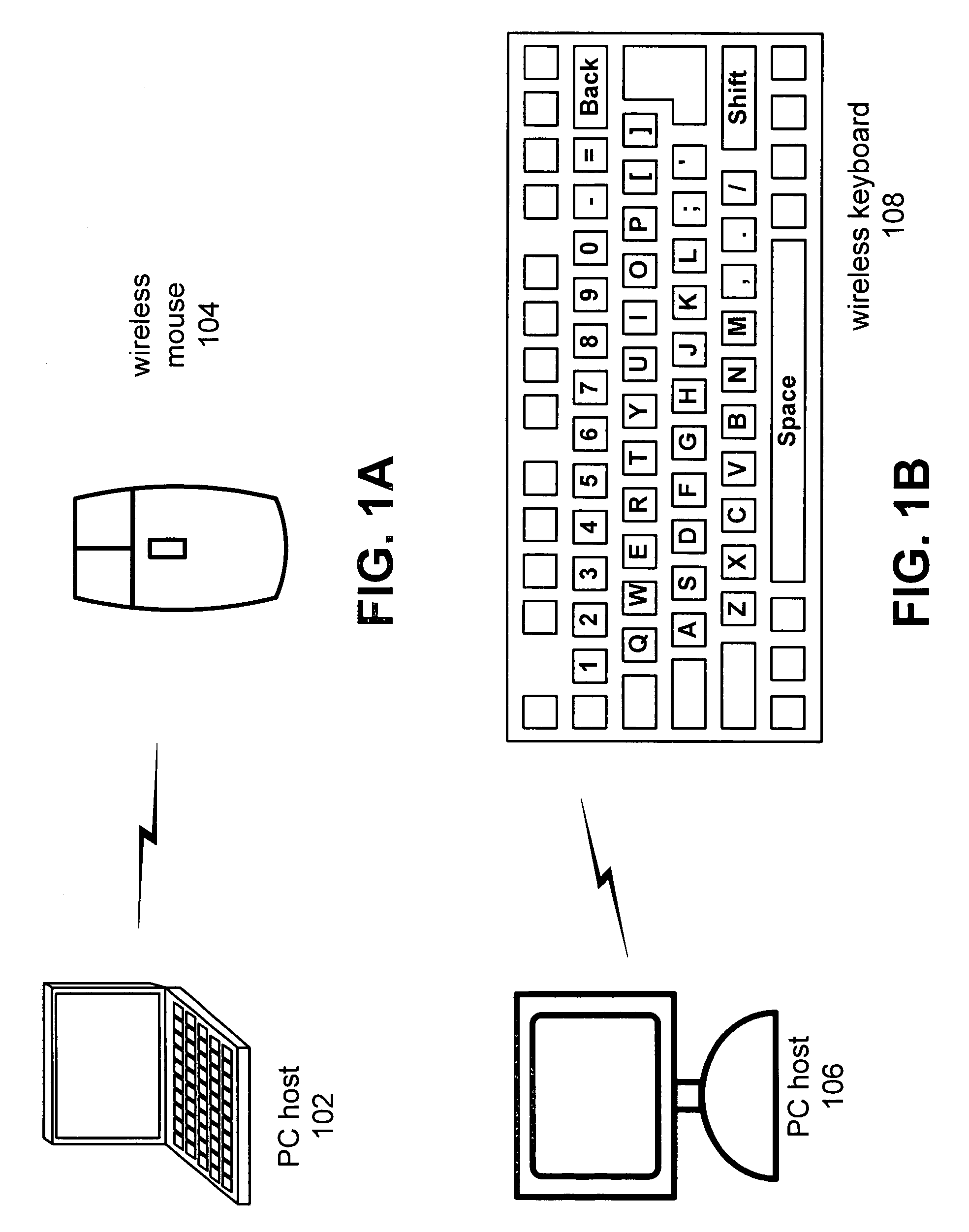
[0028]FIG. 1A is a system diagram illustrating a PC host 102 and a wireless mouse 104 that includes a wireless interface device constructed according to the present invention. As shown in FIG. 1A, the PC host 102 wirelessly couples to the wireless mouse 104. In the structure of FIG. 1A, the wireless mouse 104 includes a wireless interface device that operates to place the wireless mouse in any of a number of reduced power operating modes, including a power down mode in which battery life is substantially extended.

[0029]FIG. 1B is a system diagram illustrating a PC host 106 and a wireless keyboard 108 that includes a wireless interface device constructed according to the present invention. The wireless keyboard 108 is battery powered and operates for extended periods of time on a single set of batteries because of the greatly reduced power consumption operations according to the present invention.

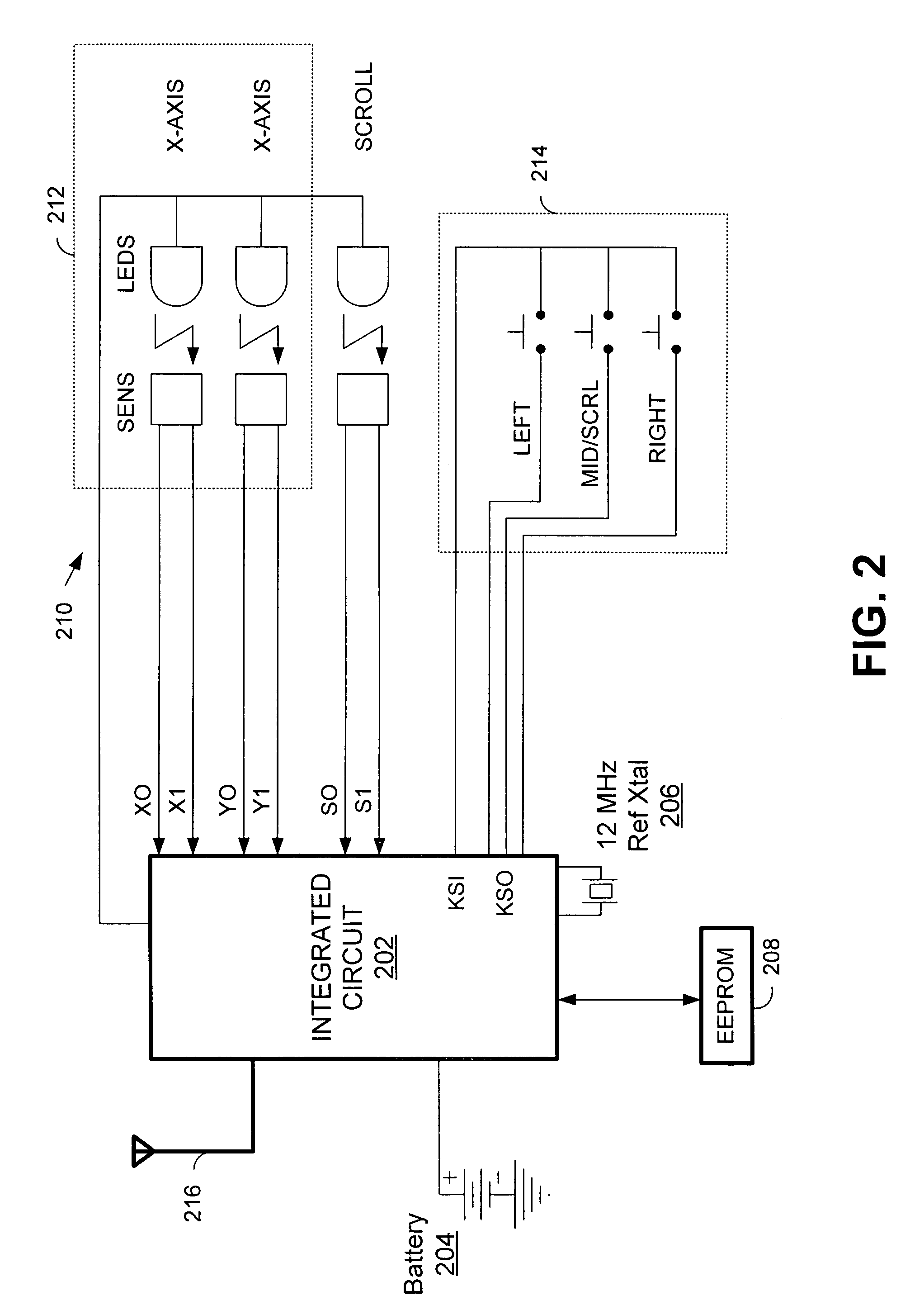
[0030]FIG. 2 is a schematic block diagram illustrati...


PUM


Abstract

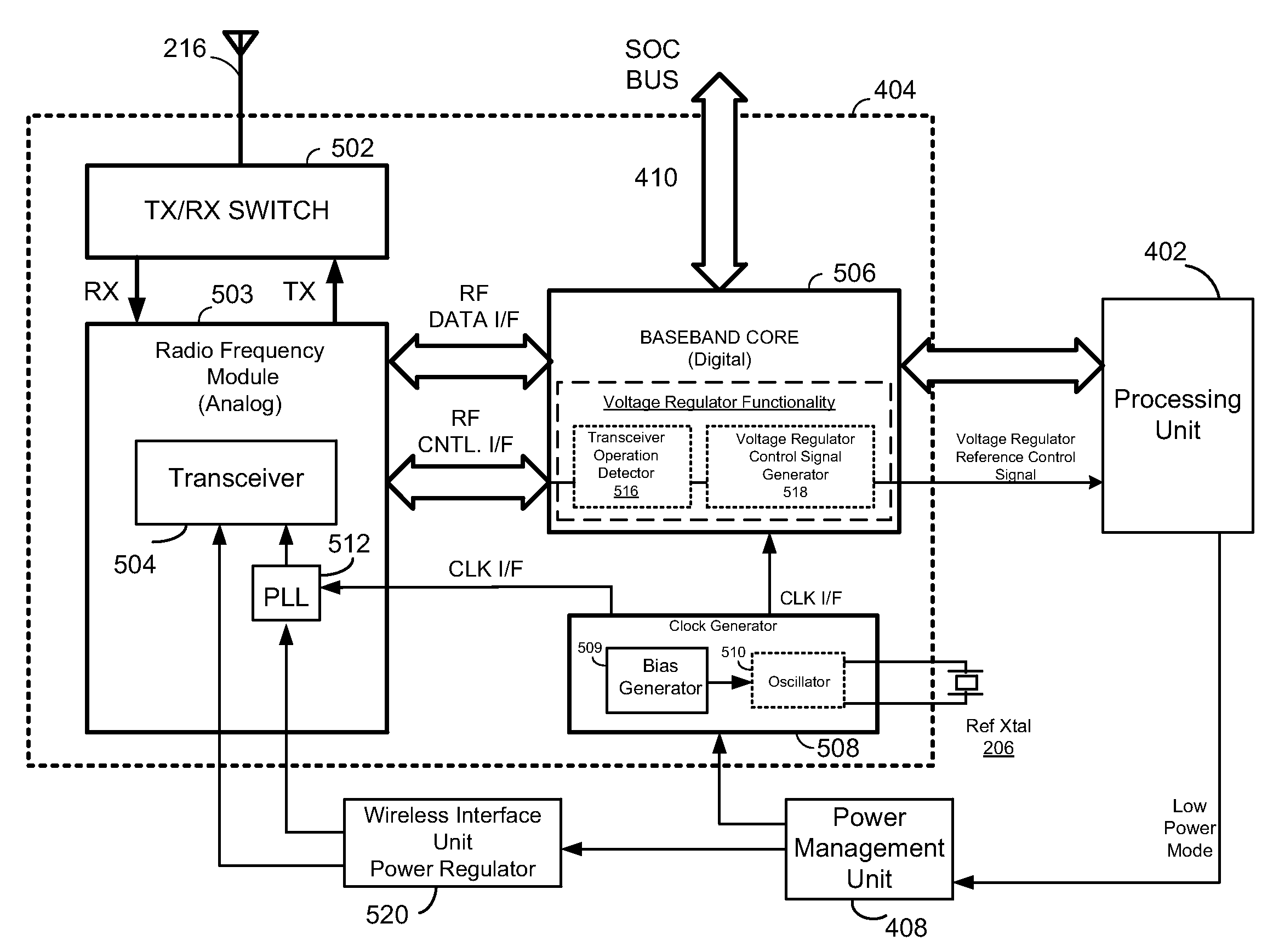
A dual mode clock for providing first and second clock signals to a wireless interface unit. The first and second clock signals correspond to first and second operating states of the wireless interface unit. In the first operating state, the transceiver in the RF analog module is operational and the clock generator provides a first clock signal having low phase-noise characteristics necessary to maintain efficient operation of the transceiver. In a second operating state, the transceiver in the RF analog module is turned off. In this second operational state, the clock generator provides a second clock signal having a quality sufficient to maintain efficient operation of the digital baseband module in the wireless interface. By switching between low-power mode and normal mode, the system is operable to provide a high quality clock signal for use by the RF analog module when it is operational and to provide a lower power, lower quality clock signal which is sufficient for use by the baseband digital unit when the transceiver in the RF analog module is powered down.

Description

BACKGROUND[0001]1. Technical Field[0002]The present invention relates generally to digital computers; and more particularly to wireless interface devices coupled to digital computers.[0003]2. Related Art[0004]Wireless communication technology has advanced rapidly over the past few years. One of the most promising areas for the use of wireless technology relates to communications between input / output devices and their “host” computers. For example, wireless keyboards and mice now couple via wireless connections to their host computers. These “wireless” input devices are highly desirable since they do not require any hard-wired connections with their host computers. However, the lack of a wired connection also requires that the wireless input devices contain their own power supply, i.e., that they be battery powered. In order to extend the life of their batteries, the wireless input devices often support power saving modes of operation. Some techniques for conserving power, however, c...

Claims


Application Information

Patent Timeline
IPC IPC(8): H04B1/16G06F1/32G06F3/023H04L12/56H04M1/72412H04M1/73
CPCG06F1/3215G06F1/324G06F1/325G06F1/3259G06F1/3271G06F3/0231H04W52/029Y02B60/148Y02B60/1217Y02B60/1253Y02B60/1257Y02B60/50H04M1/7253Y02D10/00Y02D30/70H04M1/72412
Inventor HULVEY, ROBERT W.
Owner AVAGO TECH INT SALES PTE LTD
Learn More