Vehicle condition monitoring system

a condition monitoring and vehicle technology, applied in the direction of navigation instruments, instruments, anti-theft devices, etc., can solve the problems of confused users sometimes misusing, vehicle in a decreased security condition, and not necessarily improving the convenience of users with smart keys, so as to reduce the risk of vehicle theft

Inactive Publication Date: 2008-01-22
DENSO CORP
View PDF10 Cites 39 Cited by
  • Summary
  • Abstract
  • Description
  • Claims
  • Application Information

AI Technical Summary

Benefits of technology

[0014]The vehicle condition monitoring system may be equipped with a time keeping function that keeps an elapsed time since the vehicle is parked. The vehicle condition monitoring system may send the warning after a predetermined period of time of parking. In this manner, an annoying or misplaced warning while unloading luggage or picking up a leftover luggage just after parking is avoided. This function contributes to a reliability of the vehicle condition monitoring system by preventing a false abnormal signal while the user is still staying around the vehicle.
[0015]The vehicle condition monitoring system may be equipped with a user detection function that detects the user of the vehicle in a proximity of the vehicle. The vehicle condition monitoring system warns the user only when the user is not detected in the proximity of the vehicle. In this manner, the user of the vehicle staying close to the vehicle for a rest in a parking area of a highway, for example, is not warned by the abnormal signal. This function contributes to a reliability of the vehicle condition monitoring system by avoiding a false abnormal signal while the user is staying around the vehicle.
[0016]The vehicle condition monitoring system may include an initial setting arrangement function that allows the user of the vehicle to determine the initial setting of the vehicle stored in the initial setting storage means. This function may make the initial setting stored in the initial setting storage means suitable to an actual parking manner by the user of the vehicle. Therefore, a misplaced warning for a user who, for example, intentionally parks the vehicle unlocked is avoided.
[0019]The vehicle condition monitoring system may have the initial setting storage function and the actual state detection function in the automotive device installed on the parked vehicle. These functions may allow the user of the vehicle to set or change the initial setting by using the portable device or the relay station of the wireless communication network. A change or a new setting of the initial setting may securely be stored in the vehicle condition monitoring system on the vehicle, and the change or the new setting may promptly be reflected on the initial setting and may promptly be used for comparison with the actual state. These functions installed on the vehicle may also contribute to a quick and reliable detection of the actual state of the vehicle.
[0022]The vehicle condition monitoring system may include a plurality of lock functions, a lock ID storage function, a lock ID transfer function, a lock ID receiving function, an output device storage function and a portable device selection function. The lock function installed on the door locks and unlocks the door of the parked vehicle, the lock ID storage function stores a lock ID for identifying the lock function, the lock ID sending function sends the lock ID to the automotive device on the parked vehicle, and the lock ID receiving function installed on the automotive device receives the lock ID. Then, the lock ID is stored in the output device storage function, and is used by the portable device selection function for choosing one of the portable devices as a destination of the abnormal signal. In this manner, plural portable devices may be memorized using the lock IDs, and the destination of the abnormal signal sent by the reporting function may be variably chosen according to different situations. This contributes to an improved convenience of the user of the parked vehicle.
[0024]The vehicle condition monitoring system may include a portable device location detection function, a location retrieval function, a location storage function and a distance calculation function. The portable device location detection function detects a location of the portable device, and the location retrieval function retrieves a location of the portable device detected by the portable device location detection function. The location storage function stores a locational information of the portable device, and the distance calculation function calculates a distance between a current location of the vehicle and the retrieved location of the portable device. The portable device selection function selects the portable device that is closest to the vehicle as the destination of the abnormal signal sent out by the reporting function. In this manner, the user who is closest to the vehicle may receive the abnormal signal, and thus the condition of the vehicle may quickly be checked for taking a proper action or the like. This may contribute to decrease of a risk of vehicle theft.

Problems solved by technology

However, the smart key system does not necessarily improve the convenience of the user when the operation of the portable device is too complicated or an indicator of the device is ambiguous.
Further, a confused user sometimes misuses those features to leave the vehicle in a decreased security condition, that is, the user leaves the vehicle in an unlocked condition.
Those features also contribute to an increase of battery consumption.
However, the user sometimes fails to respond to the warning because of disturbance of an environment such as a noise or the like.
In addition, some user who habitually parks the vehicle in an unlocked condition may feel it a “misplaced warning” when he / she is warned that the vehicle is left unlocked or the like.
Further, the indicator or the buzzer is only effective to the user in a proximity of the vehicle.

Method used


Image

  • Vehicle condition monitoring system
  • Vehicle condition monitoring system
  • Vehicle condition monitoring system

Examples


first embodiment

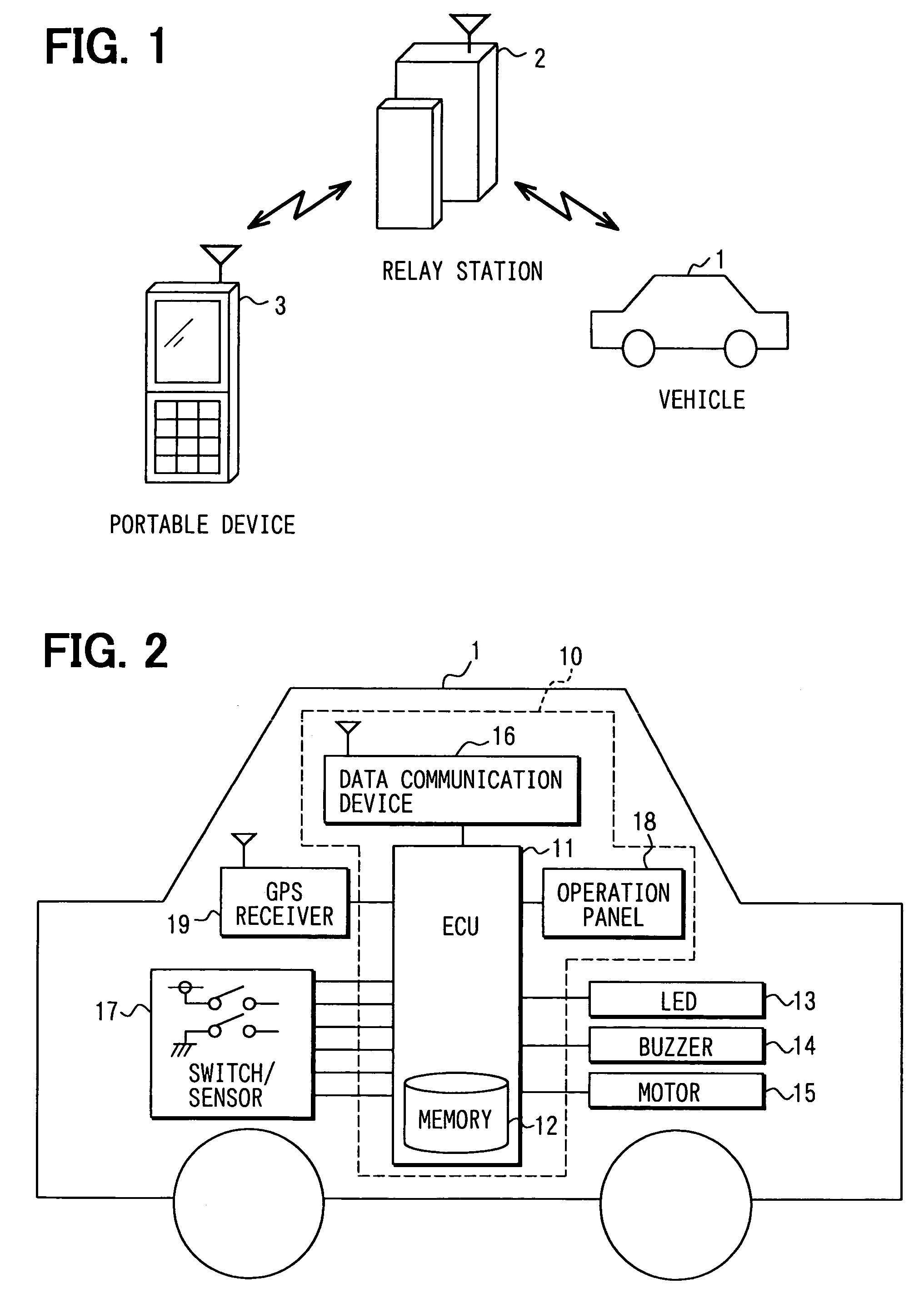
[0039]The vehicle condition monitoring system shown in FIG. 1 includes a vehicle 1 and a portable device 3. The portable device 3 in this embodiment is represented as a cell phone of a well-known type. The portable device 3 may also be a personal computer, a personal digital assistant, a transmitter (i.e., a key) of a wireless door lock having a reception function or any other device that is equipped with a communication function.

[0040]The automotive device 10 installed on the vehicle 1 is explained with reference to FIG. 2. The automotive device 10 includes an ECU (Electric Control Unit) 11 and a data communication device 16. The ECU 11 includes various components (not shown in the figure) such as a CPU, a ROM, a RAM of well-known types, an I / O circuit, a bus line, a signal circuit for switch / sensor 17, an operation panel 18, an indicator LED 13, a buzzer 14 and a signal output circuit of a motor 15. The CPU is controlled by a program and data stored in the ROM and the RAM. The ROM...

second embodiment

[0061]The initial setting of the vehicle may be set by using the portable device such as the cellular phone or the like. The portable device receives the warning when the actual state is different from the initial setting. The portable device and vehicle of this second embodiment may be represented by the portable device 3 and the vehicle 1 of the first embodiment illustrated in FIG. 1.

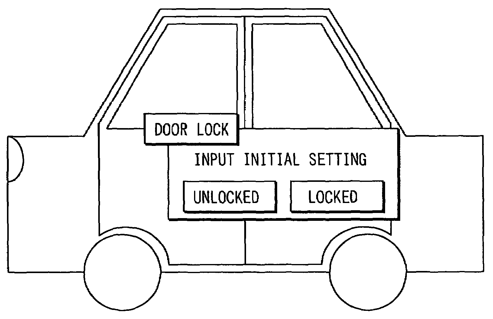
[0062]The portable device 3 may be used to set the initial setting of the vehicle 1 in this embodiment. An input window for the initial setting may be displayed on a display of the portable device by an input from a dial key or a function key of the portable device for allowing the user of the vehicle to specify the initial setting of the door (open / closed), the time slot for activating the initial setting, the place for activating the initial setting and the like. The initial setting may be sent to the automotive device on the vehicle 1 when, for example, a “Complete” button is pressed. The automotiv...

third embodiment

[0065]The portable device and the vehicle can be relayed by using a relay station. The vehicle 1, a relay station 2 and the portable device 3 in FIG. 1 collectively represent a scheme of this embodiment. The vehicle 1, the relay station 2 and the portable device 3 are communicatively connected through the wireless communication network. The portable device 3 in this embodiment is a well-known type cellular phone. The portable device 3 may also be a personal digital assistant (PDA), a transmitter of a wireless door lock having a reception function, or any other device that is equipped with a communication function.

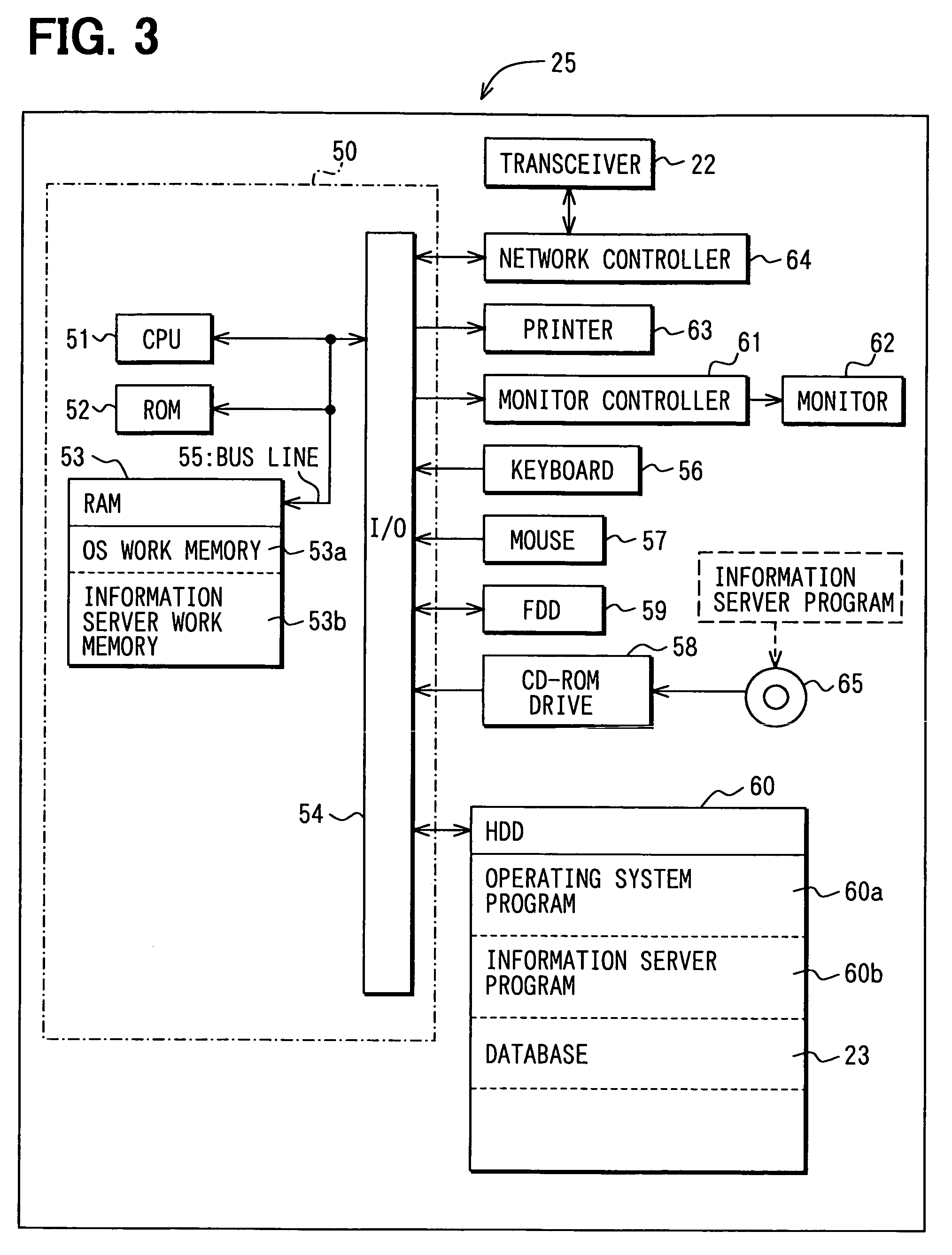
[0066]First, the relay station 2 is explained. The relay station 2 includes an information server 25 and a transceiver 22 that exchanges data with the data communication device 16 on the vehicle 1.

[0067]An example of the information server 25 is shown in FIG. 3. The information server 25 includes a CPU 51, a ROM 52, a RAM 53 and an input / output interface (I / O) 54, collectiv...


PUM


Abstract

A vehicle condition monitoring system for an unattended vehicle includes an initial setting storage means, an actual state detection means, a comparison means, and a reporting means. The initial setting storage means memorizes a predetermined initial setting of a vehicle, that is, a window setting, a light setting, a door lock setting and the like. The actual state detection means detects an actual state of the vehicle. The comparison means compares the initial setting and the actual state of the vehicle. The reporting means issues a report that identifies the existence of a difference between the actual state of the vehicle and the initial setting based on a result of a comparison. A portable device receives the report through a wireless communication system.

Description

CROSS REFERENCE TO RELATED APPLICATION[0001]This application is based on and claims the benefit of priority of Japanese Patent Application No. 2004-178902 filed on Jun. 16, 2004 and Japanese Patent Application No. 2004-230846 filed on Aug. 6, 2004, the disclosure of which is incorporated herein by reference.FIELD OF THE INVENTION[0002]The present invention generally relates to a vehicle condition monitoring system.BACKGROUND OF THE INVENTION[0003]A conventional keyless entry system, that is, a system for remotely controlling a door lock, uses a portable device attached to a key to transmit a control signal to a control unit for locking / unlocking a door on a vehicle. The portable device enables a user of the vehicle to lock / unlock the door without inserting the key in a key cylinder.[0004]A modified type of the keyless entry system, that is, a so-called smart entry system, automatically sends out a signal from the portable device to the control unit to unlock the door on the vehicle ...

Claims


Application Information

Patent Timeline
Patent Type & Authority Patents(United States)
IPC IPC(8): G01C21/00B60R16/02B60R16/023B60R25/01B60R25/10B60R25/102B60R25/31B60R25/34G06F19/00G07C5/00G07C5/08G08B25/00G08B25/10H04M11/00H04W4/00H04W4/02H04W4/04
CPCB60R16/0232B60R25/1004B60R25/102G07C5/008G07C5/085B60R2325/205
Inventor KANDA, YASUSHITERASHIMA, NORIAKIKATOU, TATSUYA
Owner DENSO CORP
Why Eureka
Try Eureka