Explosive tube removal device

a tube and explosive technology, applied in the field of metal working, can solve the problems of tube stub section, tube damage, cutting torch use errors, etc., and achieve the effect of increasing down-time and repair time, and easy breaking

Inactive Publication Date: 2008-01-29
BABCOCK & WILCOX CANADA LIMITED
View PDF39 Cites 0 Cited by
  • Summary
  • Abstract
  • Description
  • Claims
  • Application Information

AI Technical Summary

Benefits of technology

[0013]It is another object of the present invention to provide a quick means for removing a tube which has been expanded within a hole in a drum or plate of a boiler or the like.
[0014]It is a further object of the present invention to eliminate the need for complex mechanical cutting, gripping, and extracting devices which can easily be broken, thereby increasing down-time and repair time.

Problems solved by technology

These methods have often resulted in damage to the drum and the opening through which the tube stub section projected.
Errors in use of the cutting torch can, of course, damage the tube sheet requiring expensive refinishing and repair work.
The primary problem with all these prior art structures is that they impose an expansion force on the tube precisely at the point where it is engaged with the tube sheet which can damage the metal between adjacent holes and cause the holes in the tube sheet to enlarge and not properly grip a new tube when it is expanded.
Moreover, the prior art devices require additional moving parts which increase the likelihood of malfunctions and breakage of the device, which results in an increase of down-time of the structure for repairs.
These prior art devices have complex and bulky structures comprised of a plurality of moving parts subject to easy breakage and expensive repair.
As of yet, an explosive device has not been taught or suggested for removing tubes which have been expanded into fluid-tight pressure contact within a hole in a boiler, heat exchanger or the like.

Method used


Image

  • Explosive tube removal device
  • Explosive tube removal device

Examples


Embodiment Construction

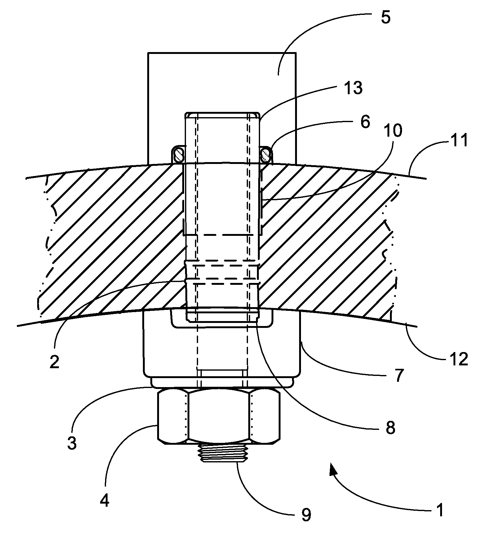
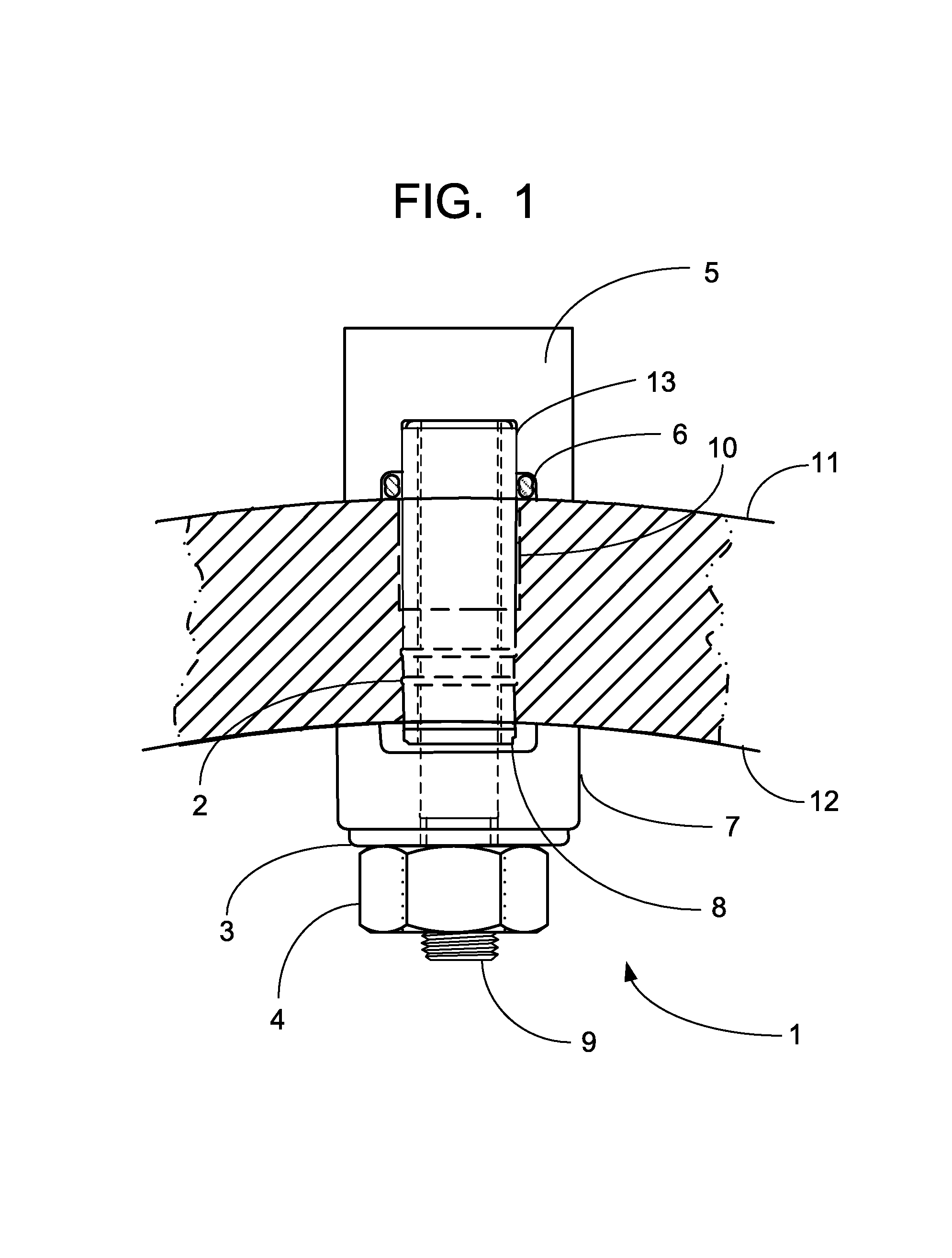
[0019]Referring now to the drawing, in which like reference numerals are used to refer to the same or similar elements, FIG. 1 shows an explosive tube removal device placed over a tube 8 for removing the tube 8 from a hole 10 within about a 4″ metal drum or plate having an outer surface diameter 11 and an inner surface diameter 12. The tube 8 has been expanded into fluid-tight pressure contact within the hole 10. Furthermore, tube 8 has been expanded into ring grooves 2 in the walls of the drum surrounding the hole 10.

[0020]The explosive removal device 1 has a top end that is above the hole 10 and outer surface diameter 11 and a bottom end that is below the hole 10 and inner surface diameter 12.

[0021]The explosive removal device 1 further comprises a cylindrical connecting rod 9 which is inserted within the tube 8 which is expanded within hole 10. The connecting rod 9 is longer than the hole 10 and tube 8 and extends beyond the top and bottom ends of both hole 10 and tube 8.

[0022]At...


PUM

PropertyMeasurementUnit
diameteraaaaaaaaaa
explosive chargeaaaaaaaaaa
diameteraaaaaaaaaa

Abstract

A explosive device is disclosed for collapsing an expansion-fit metal tube from within a hole of a metal plate of a boiler or the like. The device includes a connecting rod inserted into the tube and extending outwardly from top and bottom ends of the tube. The portion of the connecting rod extending out of the top end of the tube is encapsulated by a blast chamber containing an explosive charge. The portion of the connecting rod extending out of the bottom end of the tube is secured via a retaining plate held by a washer and nut threaded to the connecting rod.

Description

FIELD AND BACKGROUND OF INVENTION[0001]The present invention relates generally to the field of metal working and in particular to an improved tube extracting device for facilitating the removal of tubes from different types of structures, such as boilers, condensers, evaporators, heat exchangers, and the like.[0002]A typical heat exchanger comprises a pair of parallel tube sheets, a plurality of baffle plates, and a plurality of heat exchanger tubes. The tube sheets are located at the ends of the heat exchanger. The baffle plates are positioned between the tube sheets and generally parallel thereto. The tubes extend between the tube sheets and through the baffle plates and are supported by the tube sheets. The tube sheets and baffle plates have a series of aligned holes formed therein, and the tubes are inserted through these holes and then expanded in the areas of the tube sheets into fluid-tight pressure contact therewith.[0003]Because of malfunctions or normal preventive maintena...

Claims


Application Information

Patent Timeline
Patent Type & Authority Patents(United States)
IPC IPC(8): B23P19/02B25C1/08
CPCB23P19/025B25B27/062Y10T29/49822Y10T29/53113Y10T29/49352Y10T29/49821Y10T29/5199Y10T29/49806Y10T29/49815Y10T29/53843Y10T29/53122Y10T29/53987Y10T29/53
Inventor GRAY, LUKE G. M.
Owner BABCOCK & WILCOX CANADA LIMITED
Why Eureka
Try Eureka