Architecture for a multichannel geophysical data acquisition system and method of use

a geophysical data and multi-channel technology, applied in the field of electrical resistivity tomography (ert) systems, can solve the problems of unintelligible or useless data, time-consuming use, and careless attention, and achieve the effects of enhancing the physical stability of the nodes, enhancing the accuracy of current and voltage measurements, and avoiding excessive downtime and expensive field repairs

Active Publication Date: 2022-05-03
EARTHSYST TEHNOLOGIES INC
View PDF86 Cites 1 Cited by
  • Summary
  • Abstract
  • Description
  • Claims
  • Application Information

AI Technical Summary

Benefits of technology

[0032]In the event of damage to a sensor or damage to an interconnecting cable, a replacement sensor or cable may be added to the array of sensors without excessive downtime and expensive field repairs because all of the nodes are identical and are un-serialized. Further, provisions are made for single channel testing which eliminates the necessity for repeating an electrode survey after a node malfunction.
[0033]A preferred embodiment system further comprises a novel enclosure cooling system, including strategically placed ducting and insulation, which maintains proper and consistent controller temperature in elevated temperature ambie

Problems solved by technology

One of the main drawbacks to this type of system, is that the cable segments must be connected with very careful attention to the order in which they are connected.
This makes them time consuming to use.
Further, the cable sections and nodes can potentially fail during use, resulting in unintelligible or useless data.
Further, the data collection provided by these systems can be limited because of the relatively slow speed of the mechanical relays in each survey node and data contention on the single communication line.
One potential drawback to this type system is that the various controllers all share a common ground with the high voltage supply line.
The common ground makes data acquisition and communication difficult due to noise created by the high voltage and current values necessary to impress current into the injection probes.
The process used by the controller requires a communication with each node and so is relatively time consuming.
Data acquisition in this system is relatively slow due to the communication protocols used which can cause faulty data.
Further, voltage measurement by the probes requires

Method used


Image

  • Architecture for a multichannel geophysical data acquisition system and method of use
  • Architecture for a multichannel geophysical data acquisition system and method of use
  • Architecture for a multichannel geophysical data acquisition system and method of use

Examples


Embodiment Construction

[0074]In the description that follows, like parts are marked throughout the specification and figures with the same numerals, respectively. The figures are not necessarily drawn to scale and may be shown in exaggerated or generalized form in the interest of clarity and conciseness.

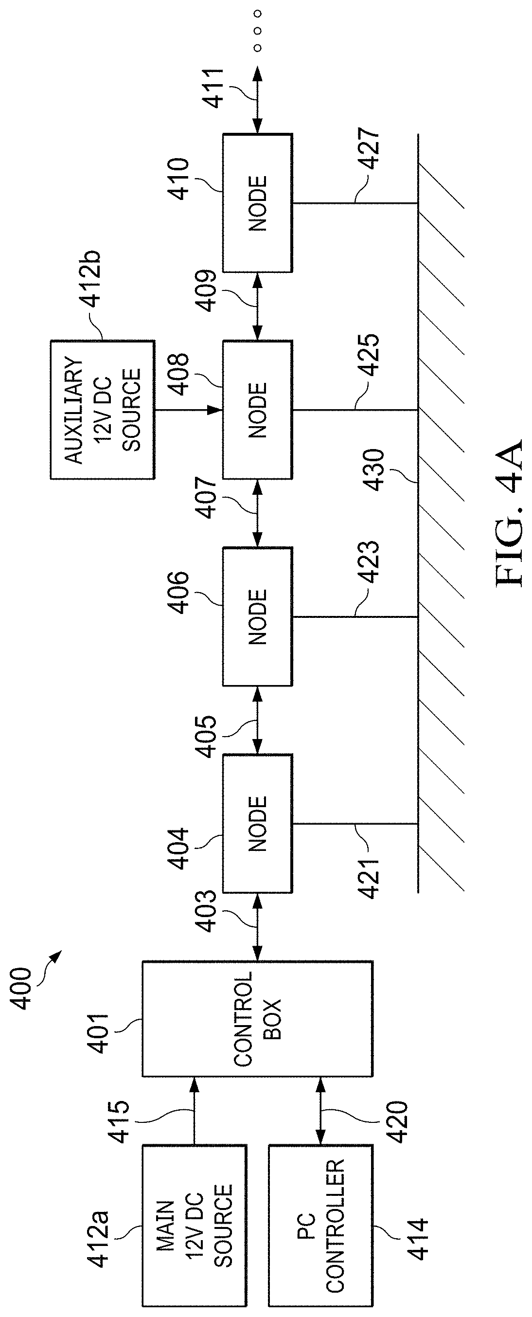
[0075]Referring to FIG. 4A, a schematic diagram of a preferred embodiment will be described. System 400 includes control box 401 connected to an upstream set of nodes 404, 406, 408 and 410. The system may have any number of nodes as indicated by the ellipses in the drawing. Node 404 is connected to control box 401 and node 406. Node 406 is connected downstream to node 408 and upstream to node 404. Node 408 is connected downstream to node 410 and upstream to node 406. Node 408 is also operatively connected to auxiliary 12V DC source 412b. Auxiliary 12V DC source 412b is provided to extend the maximum number of nodes in the array to approximately 50. However, though use of an auxiliary 12V DC source at appro...


PUM


Abstract

An architecture for a multichannel geophysical data acquisition system is provided in the field of electrical resistivity tomography. Individual and autonomous node operating systems are provided. Separate communication channels for upstream and downstream data transfer, high voltage transfer and synchronization signals are provided. A novel use of high voltage isolation barriers is also provided. A direct memory access data transfer process is provided.

Description

FIELD OF THE INVENTION[0001]The field of the invention is electrical resistivity tomography (ERT) systems for locating subsurface anomalies, such as variations in density and the presence of groundwater. Raw resistivity data is collected by a reconfigurable network of sensors that distributes current into the ground and measures resulting voltages.BACKGROUND OF THE INVENTION[0002]ERT is a geophysical technique for imaging subsurface structures using electrical resistivity measurements made by electrodes impressed in the ground.[0003]Resistivity can be computed if the intensity of a current injected into the ground, and the resulting potential difference established between measurement electrodes are known. Resistivity depends on the geometry of the electric field, the nature of the soil and the method used to measure the injected current and the resulting potential difference between the electrodes.[0004]In practice, a system of electrodes is placed in the ground in a predetermined ...

Claims


Application Information

Patent Timeline
IPC IPC(8): H04L12/40H03M1/66H04L7/00
CPCH04L12/40013H03M1/66H04L7/0008H04L12/40019H04L12/40039H04L12/40052G06F13/28H04L61/5038G01V3/02H04L12/40045H04L12/10H04L12/403H04L61/4552G01V3/20G01V3/38
Inventor BRYANT, JOHNSAVAGE, FREDERICK HERSHELBEETS, TIMOTHY
Owner EARTHSYST TEHNOLOGIES INC
Why Eureka
Try Eureka