
Combustion chamber for combusting a combustible fluid mixture

a combustible fluid and combustion chamber technology, which is applied in the direction of mechanical equipment, machines/engines, lighting and heating apparatus, etc., can solve the problems of difficult high physical stress on the liner in particular, and inability to carry out disassembly from the insid

Inactive Publication Date: 2008-01-29
SIEMENS AG
View PDF12 Cites 4 Cited by
  • Summary
  • Abstract
  • Description
  • Claims
  • Application Information

AI Technical Summary

Benefits of technology

[0008]For the first time the rails are disposed on the hot gas side and form part of the internal wall of the combustion chamber. As a result the liner joints face outward, thereby enabling the liner to be realized as a more simple and also a flatter design. Furthermore, internal stresses can be reduced. Disassembly of the liner elements toward the inside as well as assembly of the liner elements from the inside can be achieved.
[0017]In an advantageous embodiment of the present invention it is proposed that air be used as the coolant. Thus, a portion of the intake air, for example in the case of a gas turbine, can advantageously be tapped off and used for cooling. The portion of the air used for cooling is particularly advantageously fed back to the combustion chamber again such that on the one hand the heat absorbed by the cooling function and on the other hand the energy used to provide the cooling air can be returned at least partially to the process. A further increase in efficiency can be achieved.

Problems solved by technology

The liner disposed in the interior of the combustion chamber in particular is exposed to high physical stress, which is why this liner is subject to wear and tear.
The rails disposed between the liner and the casing are in fact located in a comparatively cool area of the combustion chamber, with the result that disassembly from the inside cannot easily be carried out.
All in all, however, the liner too is very complicated to manufacture due to the fixing toward the interior.

Method used


Image

  • Combustion chamber for combusting a combustible fluid mixture
  • Combustion chamber for combusting a combustible fluid mixture
  • Combustion chamber for combusting a combustible fluid mixture

Examples


Embodiment Construction

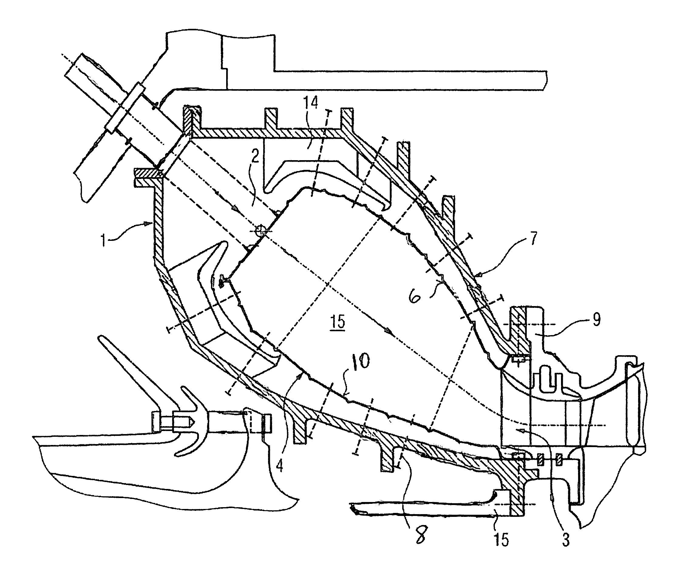
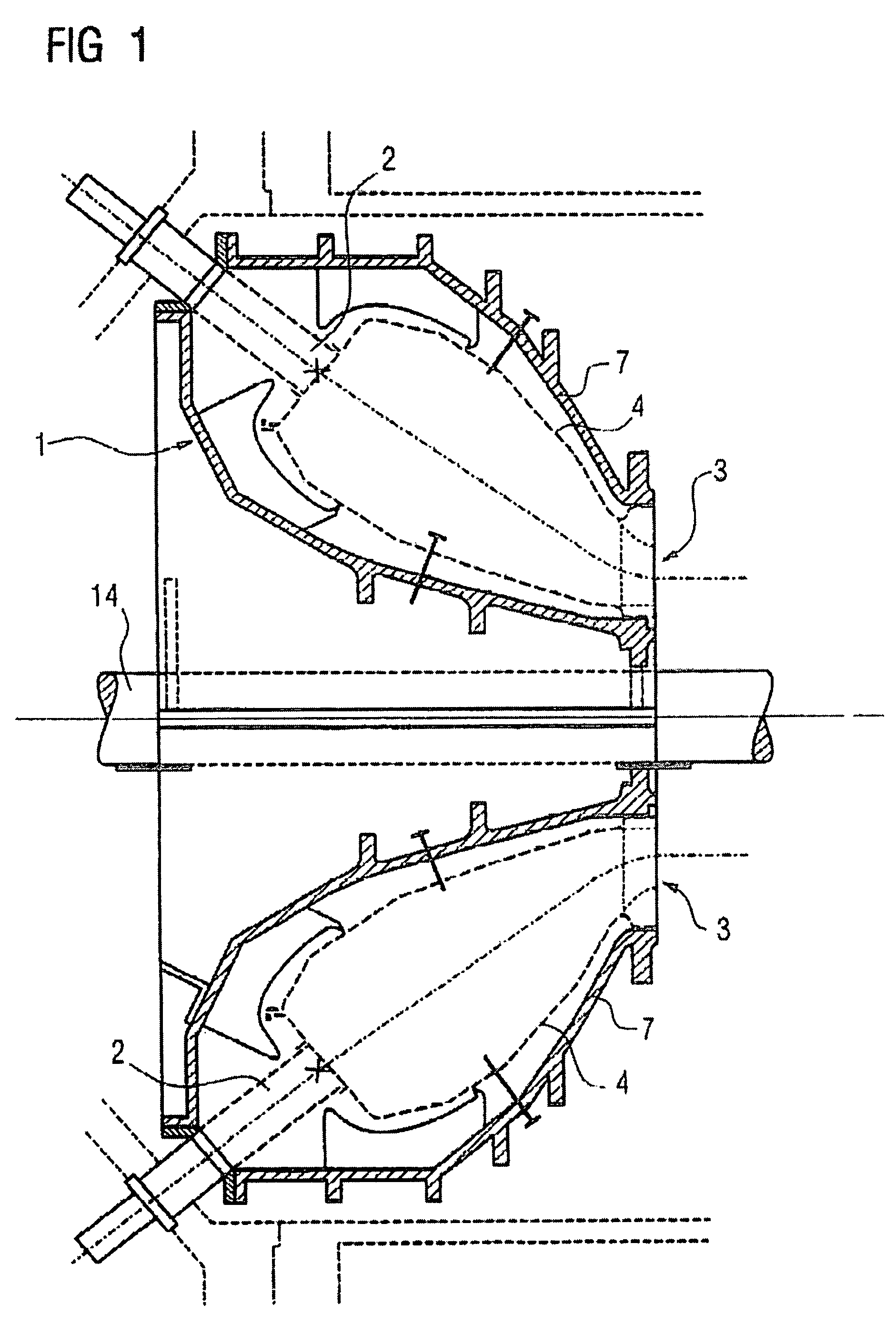
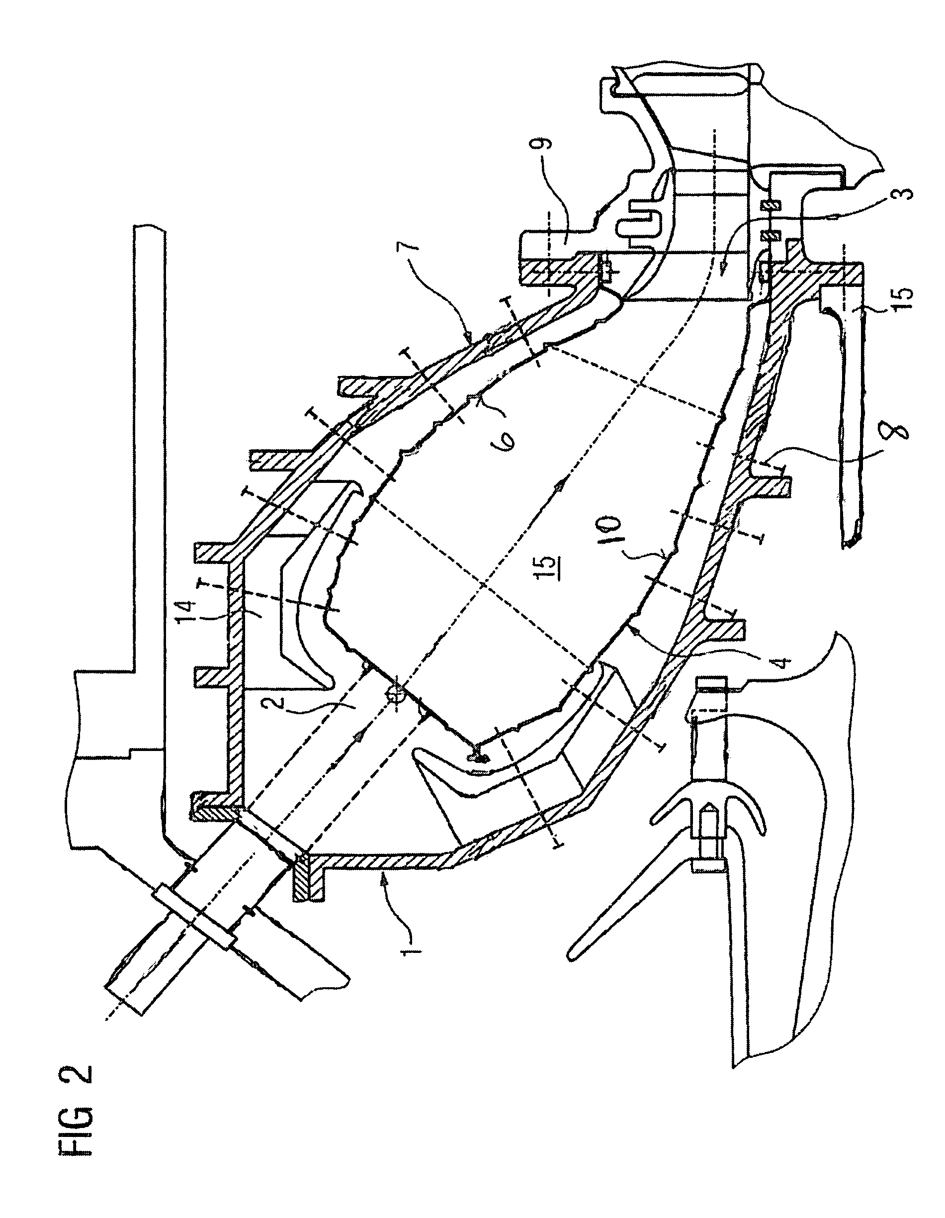
[0023]FIG. 1 shows a section of a gas turbine comprising a combustion chamber 1 according to the invention, which in the present case is implemented as an annular combustion chamber. The combustion chamber 1 has a casing 7 in which a liner 4 is disposed. Opening at one end of the liner 4 is a burner 2 via which a combustible fluid is supplied. At the opposite end of the liner there is provided an outlet opening 3 which is connected to an inlet to a flow channel of a downstream gas turbine which is not described in further detail. A rotor shaft 14 is disposed centrally. FIG. 2 shows a section through the upper part of the combustion chamber 1 on a larger scale. The combustible fluid supplied via the burner 2 is ignited in a combustor 15 in the liner 4 and flows in the direction of the outlet opening 3 to the following turbine.

[0024]The liner 4 is constructed in the form of segments from liner elements 5 which are connected to one another adjacently in each case via rail elements 6 (F...


PUM


Abstract

A combustion chamber (1) for combusting a combustible fluid mixture having a burner (2) disposed on the combustion chamber (1) and a method for cooling a combustion chamber (1). A fixing device is provided for liner elements (5) of a combustion chamber (1) by which simplified assembly from the inside of the liner (4) can be achieved. The combustion chamber has a burner (2) disposed on the combustion chamber (1), a liner (4) disposed in the combustion chamber (1), and an outlet opening (3), wherein the liner (4) includes liner elements (5) which are elastically fixable to a combustion chamber casing (7) by rail elements (6), the rail elements (6) being disposed on the combustion chamber side and projecting outward between two adjacently disposed liner elements (5).

Description

CROSS REFERENCE TO RELATED APPLICATIONS[0001]This application claims the benefits of European application No. 02026101.2 EP, filed Nov. 11, 2002, which is incorporated by reference herein in its entirety.FIELD OF INVENTION[0002]The present invention relates to a combustion chamber for combusting a combustible fluid mixture having a burner disposed on the combustion chamber. The invention further relates to a method for cooling a combustion chamber according to the invention.BACKGROUND OF INVENTION[0003]Combustion chambers, particularly for gas turbines, are usually provided internally with a flow control body which is referred to as a liner. Basically, different concepts for combustion chamber arrangements are known. Thus, for example, combustion chamber arrangements are used which are composed of a plurality of individual combustion chambers (cans) which culminate in a common opening. In the case of a gas turbine the opening is preferably implemented as an annular opening which sim...

Claims


Application Information

Patent Timeline
IPC IPC(8): F23M5/04F23R3/60F02C7/18F02C7/20F23R3/00F23R3/42
CPCF23M5/04F23R3/002
Inventor TIEMANN, PETER
Owner SIEMENS AG
Learn More