Lubrication structure of camshaft with variable valve timing

a technology of variable valve timing and lubrication structure, which is applied in the direction of valve drives, machines/engines, mechanical equipment, etc., can solve the problems of oil pressure and lubrication at an advanced side, deterioration of volatil efficiency, and damage to the journal of the camsha

Active Publication Date: 2008-01-29
HYUNDAI MOTOR CO LTD
View PDF13 Cites 11 Cited by
  • Summary
  • Abstract
  • Description
  • Claims
  • Application Information

AI Technical Summary

Benefits of technology

[0009]Embodiments of the present invention provide a lubrication structure of a camshaft with a variable valve ...

Problems solved by technology

If the intake valve is opened in advance, a valve overlap period becomes long so that intake and exhaust inertia flow can be sufficiently used at a high speed, and accordingly a volumetric efficiency is enhanced, but at a low speed, a volumetric efficiency is deteriorated because of increase of remained gas so that amount of exhausted HC gas is in...

Method used


Image

  • Lubrication structure of camshaft with variable valve timing
  • Lubrication structure of camshaft with variable valve timing
  • Lubrication structure of camshaft with variable valve timing

Examples


Embodiment Construction

[0028]Exemplary embodiments of the present invention will hereinafter be described in detail with reference to the accompanying drawings.

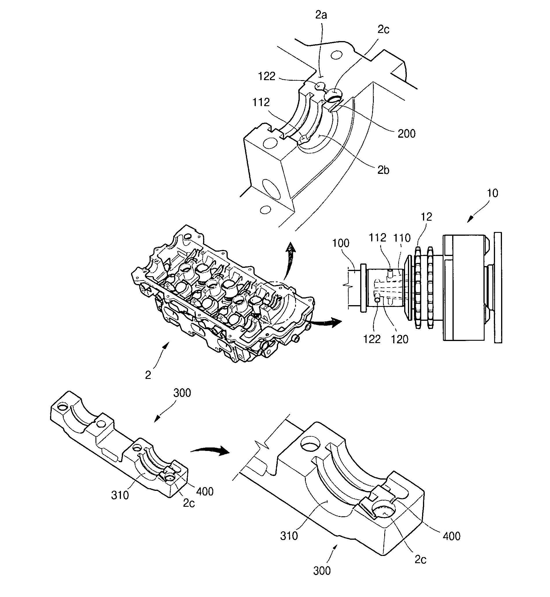
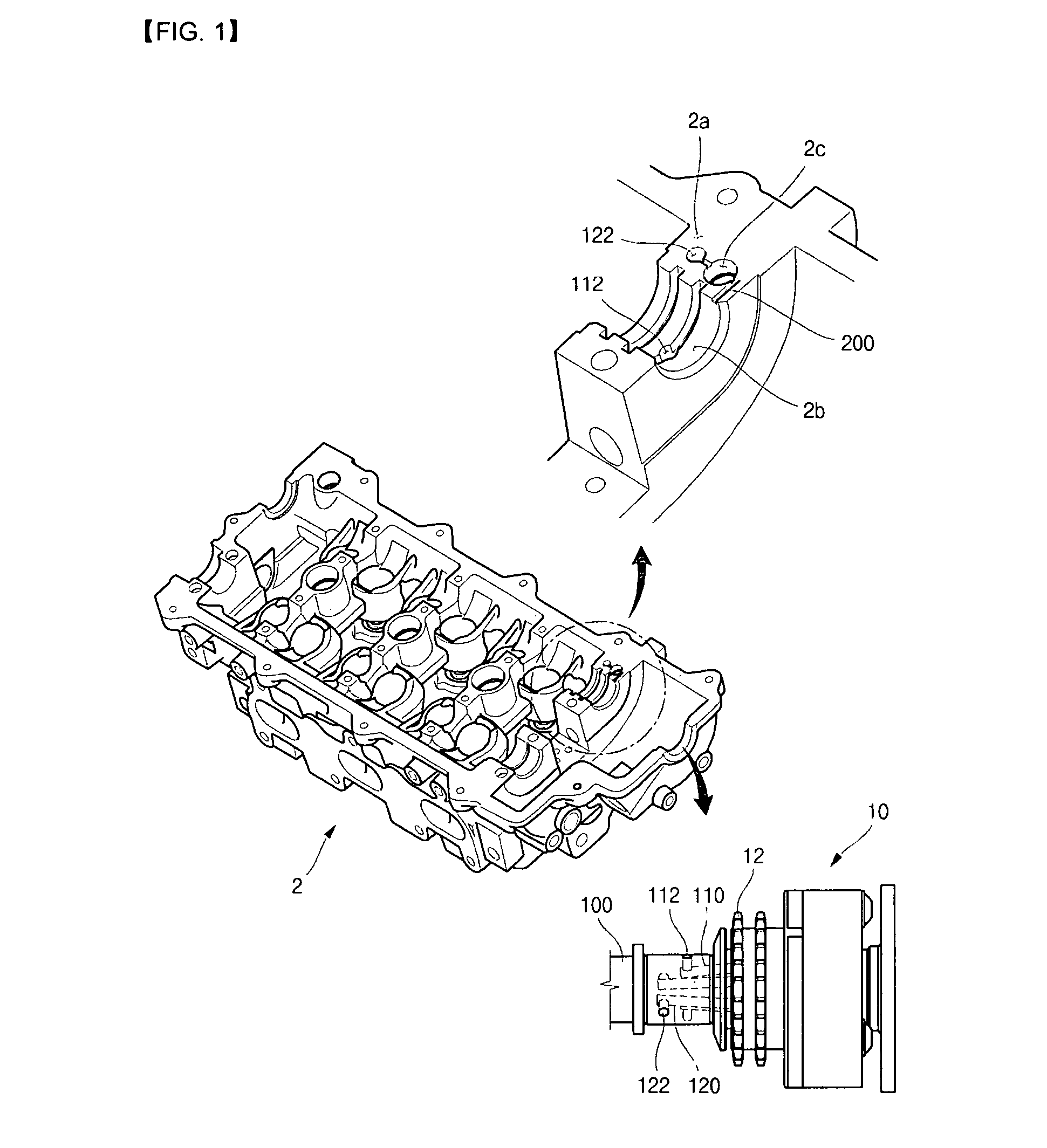
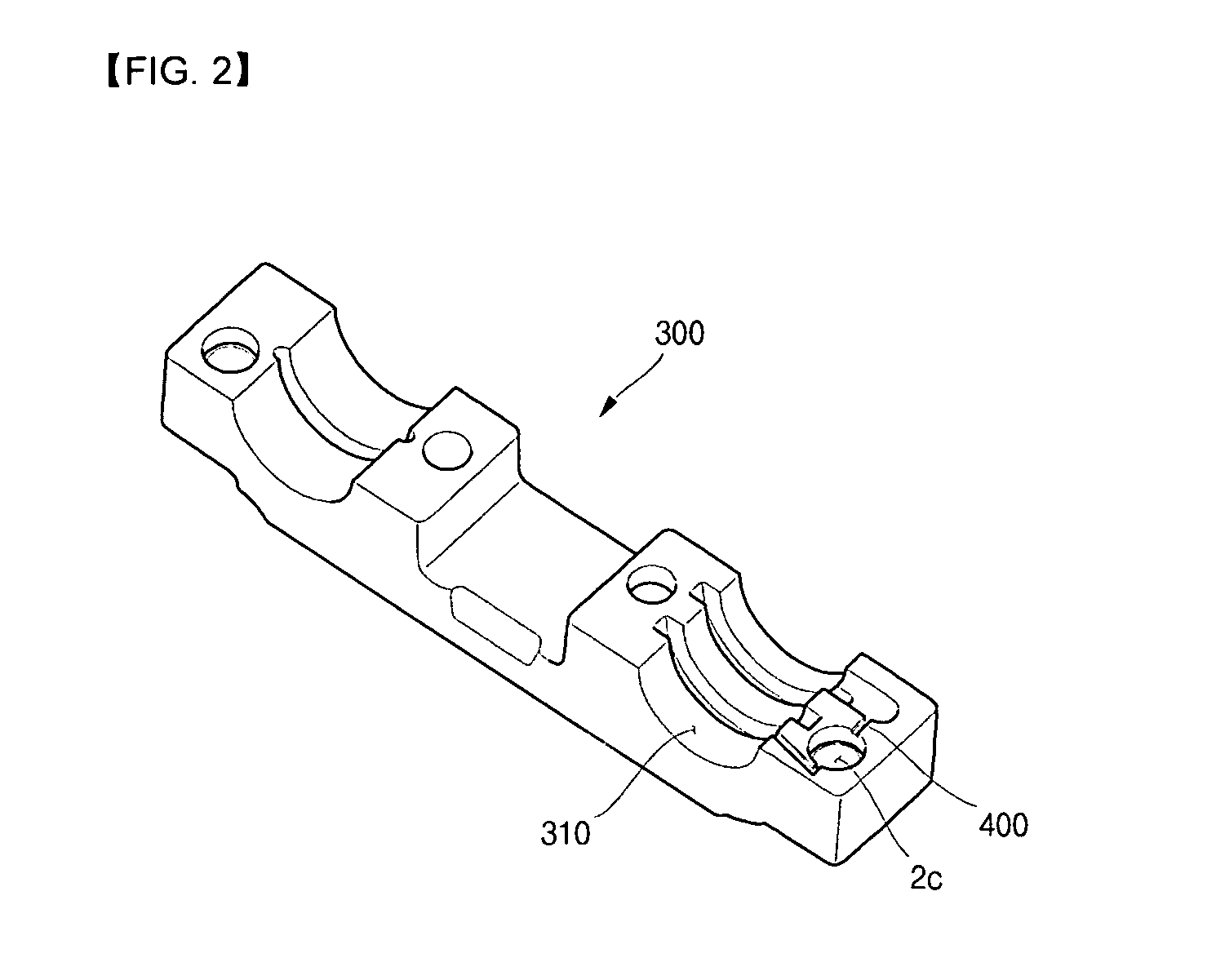
[0029]Referring to FIG. 1, a lubrication structure of a camshaft with variable valve timing according to an exemplary embodiment of the present invention includes: an advance hole 112, which includes an advance flow passage 110 formed in a camshaft body 101 near a sprocket 12, an end of a camshaft 100 inserted into a continuously variable valve timing (CVVT) assembly 10 to which the sprocket 12 is provided; a retard hole 122 which includes a retard flow passage 120 formed in the camshaft body 101 to be spaced horizontally from a position of the advance hole 112; and a divergence flow passage 200, one end of which surface-contacts the camshaft 100 and is extended to communicate with the retard hole 122 at an upper surface of a mounting part 2a of a cylinder head 2 in which a slip surface 2b is formed, and the other end of which communicates with the...


PUM


Abstract

A lubrication structure for a camshaft with variable valve timing includes an advance hole, which includes an advance flow passage formed in a camshaft body. An end of the camshaft is attached to a continuously variable valve timing. A retard hole, which includes a retard flow passage, is formed in the camshaft body and spaced horizontally from the advance hole. A divergence flow passage has an end that surface-contacts the camshaft and is extended to communicate with the retard hole at an upper surface of a mounting part of a cylinder head. The other end of the divergence flow passage communicates with the slip surface on which the camshaft lays via a counter bore, so as to prevent lubrication film from being broken by load of the sprocket at an engine idle state or at an initial stage of cold starting.

Description

CROSS-REFERENCE TO RELATED APPLICATION[0001]This application claims priority to and the benefit of Korean Patent Application No. 10-2006-0107478 filed in the Korean Intellectual Property Office on Nov. 1, 2006, the entire contents of which are incorporated herein by reference.BACKGROUND OF THE INVENTION[0002](a) Field of the Invention[0003]The present invention relates to a lubrication structure of a camshaft with a variable valve timing.[0004](b) Description of the Related Art[0005]Generally, in order to enhance an efficiency of an engine, it is required to vary opening / closing timing of valves depending on an engine speed. In particular, opening / closing timing of an intake valve is a factor having a significant effect on a volumetric efficiency. If the intake valve is opened in advance, a valve overlap period becomes long so that intake and exhaust inertia flow can be sufficiently used at a high speed, and accordingly a volumetric efficiency is enhanced, but at a low speed, a volu...

Claims


Application Information

Patent Timeline
IPC IPC(8): F01M1/06
CPCF01L1/053F01L1/34F01L2001/0476F01L2001/0537F01L2001/34479F01L1/04F01M1/06
Inventor KIM, SUC TAE
Owner HYUNDAI MOTOR CO LTD
Why Eureka
Try Eureka