Oil pan structure

a technology of oil pan and structure, which is applied in the direction of crankshafts, machines/engines, mechanical equipment, etc., can solve the problems of increasing the number of components, complicated components arrangement, and requiring additional components, and achieves the effect of simple oil pan structure and smooth oil draw up

Inactive Publication Date: 2008-01-29
TOYOTA JIDOSHA KK
View PDF13 Cites 6 Cited by
  • Summary
  • Abstract
  • Description
  • Claims
  • Application Information

AI Technical Summary

Benefits of technology

[0010]It is an object of the invention to provide a simple oil pan structure that enables an oil changer to smoothly draw oil up from the deepest portion of a reservoir portion without increasing the number of components.
[0012]According to the first aspect, the nozzle guide guides the end of the nozzle of the oil changer to the position near the deepest portion of the reservoir portion of the oil pan. As a result, the end of the nozzle is reliably guided to the deepest portion of the reservoir portion, and the oil in the reservoir portion can be more efficiently drawn up from the deepest portion. In addition, it is possible to minimize the amount of oil that remains in the deepest portion of the reservoir portion even after draw-up of the used oil ends, without employing a complicated oil pan structure.
[0013]In the first aspect, a stopper may be provided. This stopper sets the end of the nozzle of the oil changer at the position near the deepest portion of the reservoir portion. The end of the nozzle of the oil changer is reliably positioned near the deepest portion of the reservoir portion by the stopper. This prevents the end of the nozzle of the oil changer from going beyond the deepest portion, thereby deviating upward from the deepest portion. It is, therefore, possible to more efficiently draw the oil up from the deepest portion of the reservoir portion, and more effectively minimize the amount of oil that remains in the reservoir portion even after draw-up of the used oil ends.
[0015]Provision of such a guide portion prevents the end of the nozzle of the oil changer from (a) coming into contact with the bottom-wall surface of the oil pan, thereby becoming stuck at the bottom-wall surface, and (b) adopting an inappropriate orientation after coming into contact with the bottom-wall surface of the oil pan. With such a structure, the end of the nozzle of the oil changer is reliably guided to the nozzle guide by the guide portion. This structure, therefore, provides greater ease in smoothly guiding the end of the nozzle of the oil changer to the position near the deepest portion of the reservoir portion.

Problems solved by technology

However, because it is difficult to accurately determine whether the end of the oil changer is guided to the deepest portion of the reservoir portion when the oil changer draws up the oil in the reservoir portion, the following problem may arise.
If the end of the oil changer is not guided to the deepest portion, some oil remains in the deepest portion even after draw-up of the used oil ends, because the oil changer cannot efficiently draw up the oil in the reservoir portion.
According to the described approach, however, additional components are required.
This increases the number of components, and, therefore, complicates the arrangement of components.
In addition, because the through-holes are required to form the passage through which the oil changer draws up the oil, the structure of the oil pan becomes considerably complicated.

Method used


Image

  • Oil pan structure
  • Oil pan structure
  • Oil pan structure

Examples


Embodiment Construction

[0036]Hereafter, an embodiment of the invention will be described with reference to accompanying drawings.

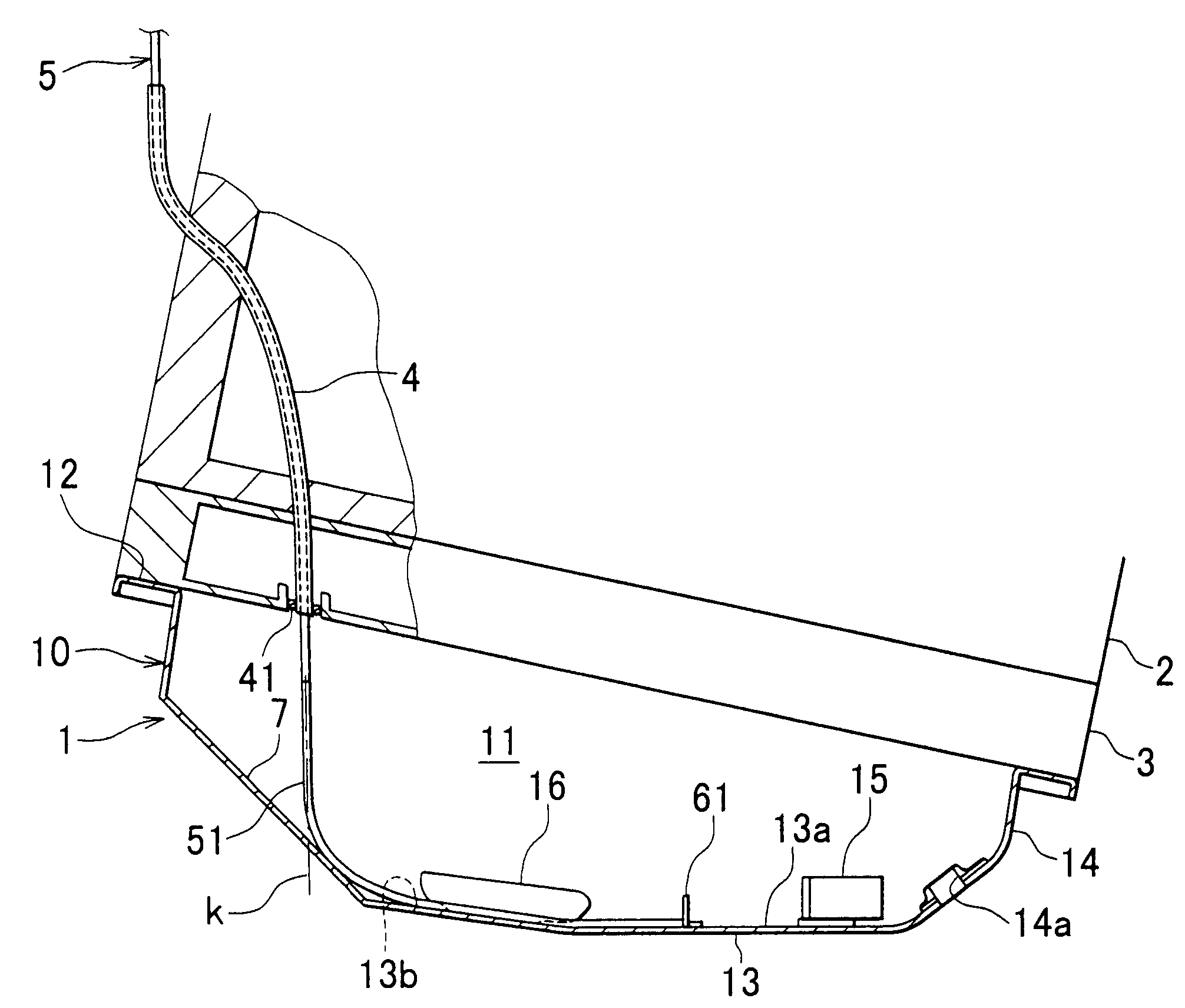
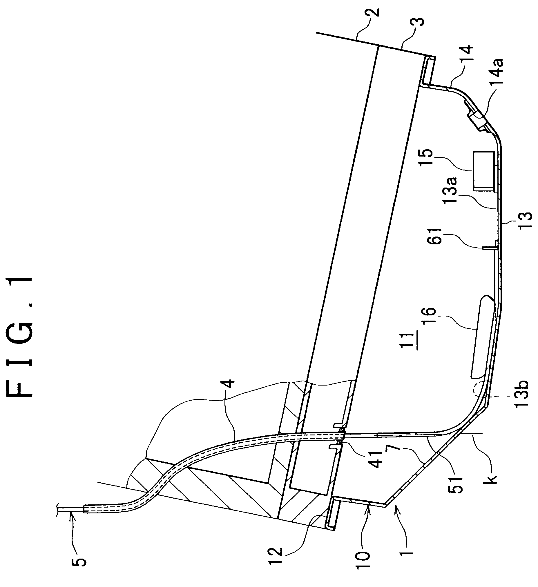
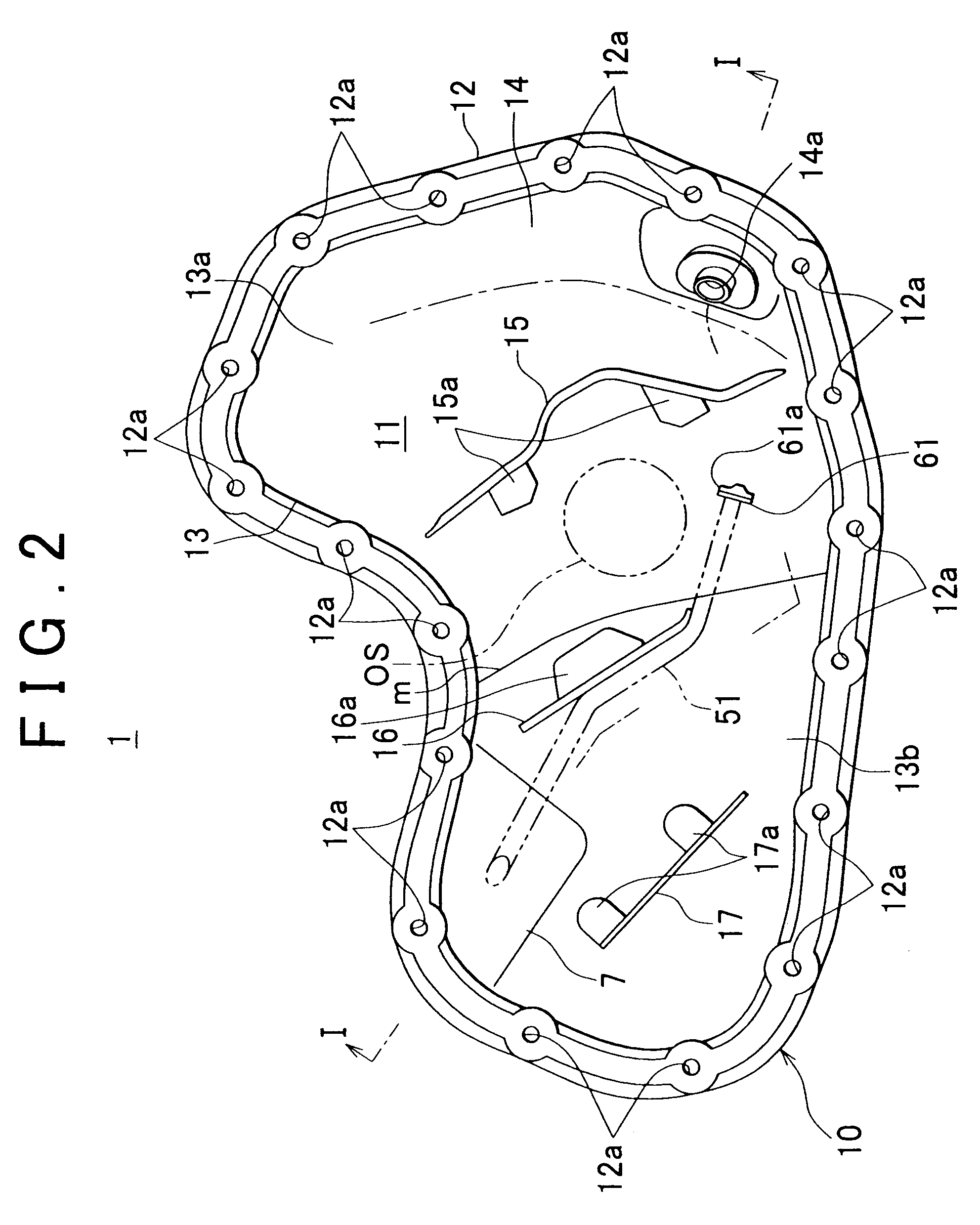
[0037]FIG. 1 illustrates the cross-sectional view of the portion near the lower portion of a cylinder-block 2 provided with an oil pan 1. FIG. 2 illustrates the plan view of the oil pan 1. The oil pan 1 is attached, via an oil pan gasket (not shown), to the bottom surface of a cylinder-block-lower-case 3 attached to the bottom surface of the cylinder-block 2 of an internal combustion engine. In this case, the internal combustion engine is mounted in a vehicle body at an incline toward the front of the vehicle. Similarly, the cylinder-block 2 and the cylinder-block-lower-case 3 are at an incline toward the front of the vehicle.

[0038]As shown in FIGS. 3 and 4, the oil pan 1 has a reservoir portion 11 in which oil can be stored when an oil pan body 10 is attached to the cylinder-block-lower-case 3. The oil pan body 10 may be formed, for example, by pressing a steel plate into the a...


PUM


Abstract

An oil pan structure includes a tubular level-gauge guide into which an oil level-gauge that measures the amount of oil stored in the oil pan is inserted. The oil pan structure further includes a nozzle guide that guides the end of a nozzle of an oil changer, which is inserted into the level-gauge-guide when the oil in the oil pan is replaced with new oil, to a position near the deepest portion of the reservoir portion.

Description

INCORPORATION BY REFERENCE[0001]The disclosure of Japanese Patent Application No. 2004-368504 filed on Dec. 20, 2004 including the specification, drawings and abstract is incorporated herein by reference in its entirety.BACKGROUND OF THE INVENTION[0002]1. Field of the Invention[0003]The invention relates to an oil pan structure.[0004]2. Description of the Related Art[0005]Usually, an oil pan is provided below the cylinder-block of an internal combustion engine used in, for example, a vehicle. This oil is used, for example, to cool, and lubricate the internal combustion engine. Such an oil pan is provided with a tubular level-gauge guide where one end opens into the reservoir portion of the oil pan, in which oil is stored. Generally, an oil level-gauge inserted in this level-gauge guide measures the amount of oil stored in the reservoir portion.[0006]When the oil in oil pan needs to be replaced with new oil, an oil changer, instead of the oil level-gauge, may be inserted into the lev...

Claims


Application Information

Patent Timeline
Patent Type & Authority Patents(United States)
IPC IPC(8): F02B77/00F16C3/14F02F7/00
CPCF01M11/045
Inventor SUZUKI, YOSHINORIKOMATSU, KOICHIROKATO, HISAYOSHI
Owner TOYOTA JIDOSHA KK
Why Eureka
Try Eureka