An oil-absorbing anti-clogging structure of an automobile electric pump

An anti-clogging, electric pump technology, applied in charging systems, machines/engines, liquid fuel feeders, etc., can solve problems such as accumulation, and achieve the effect of ensuring normal use, stable operation, and smoothness.

Active Publication Date: 2021-05-04
萧县威辰机电工程设备有限公司
View PDF3 Cites 0 Cited by
  • Summary
  • Abstract
  • Description
  • Claims
  • Application Information

AI Technical Summary

Problems solved by technology

[0005] The technical problem to be solved by the invention of this paper is how to block and divert impurities in the past to avoid the accumulation of impurities at the oil inlet. Due to the problem of oil impurity clogging, it can filter and saturate the anti-clogging structure, and still have a certain impact on the oil inlet and outlet process. The filter function ensures the normal supply of the engine for a period of time and ensures the smoothness of oil absorption, so we propose an oil absorption and anti-clogging structure for automobile electric pumps

Method used


Image

  • An oil-absorbing anti-clogging structure of an automobile electric pump
  • An oil-absorbing anti-clogging structure of an automobile electric pump
  • An oil-absorbing anti-clogging structure of an automobile electric pump

Examples


Embodiment 1

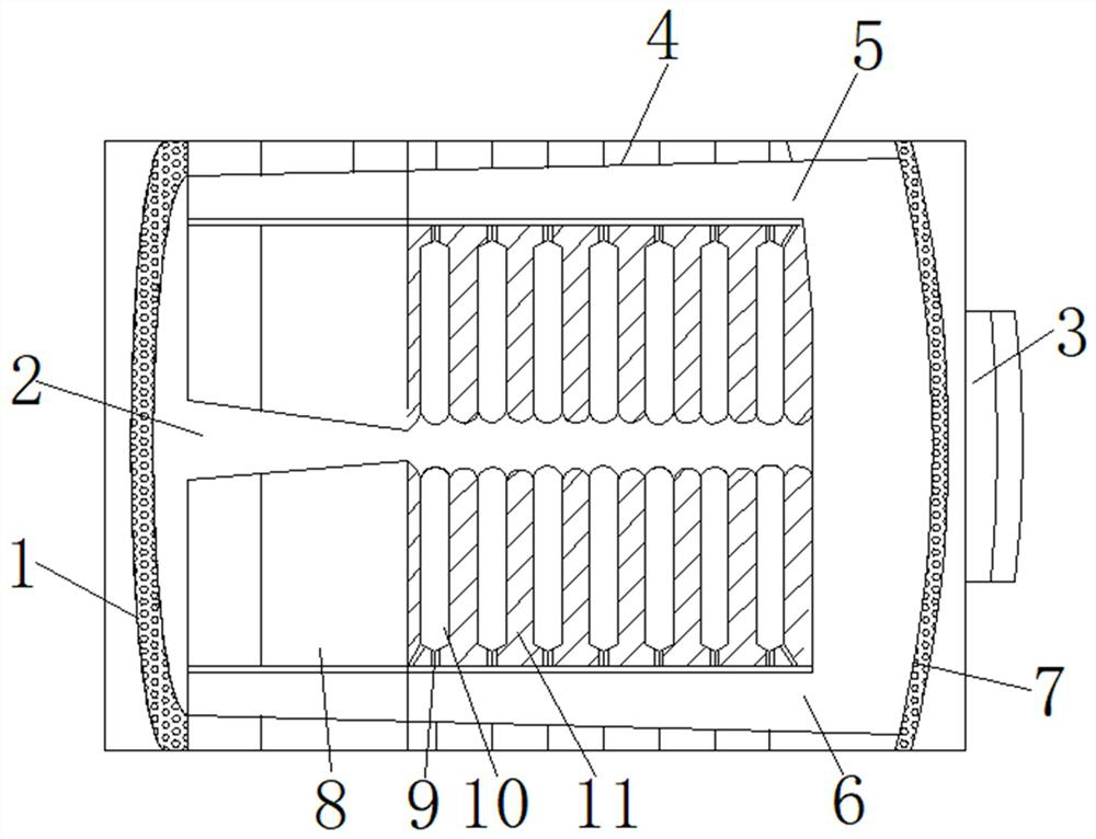
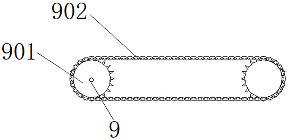
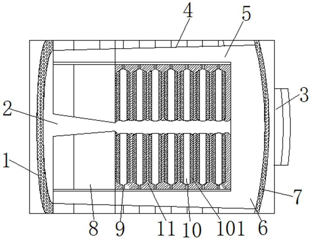
[0028] Such as Figure 1-5 As shown, it includes the oil inlet of the oil pump, and one end of the oil inlet of the oil pump is provided with a housing, and the inside of the housing includes a limit flow cavity (8) and a filter cavity, and the filter cavity includes several groups of uniformly arranged expansion arc plates (10 ) and the stacked filter plate (11), the two ends of the expansion arc plate (10) are provided with azimuth rotation column (9), and one end of the azimuth rotation column (9) is movably connected with a fixed rotation frame (12), and the azimuth rotation column ( One end of 9) is fixedly connected with a gear (901), and a motor is arranged inside the limit flow cavity (8), and a chain (902) is arranged at one end of the motor, and one end of the chain (902) is meshed with the gear (901). The laminated filter plate (11) and the expanded arc plate (10) are arranged indirectly with each other, the laminated filter plate (11) is fully close to the inner si...

Embodiment 2

[0034] Such as Figure 1-5As shown, it includes the oil inlet of the oil pump, and one end of the oil inlet of the oil pump is provided with a housing, and the inside of the housing includes a limit flow cavity (8) and a filter cavity, and the filter cavity includes several groups of uniformly arranged expansion arc plates (10 ) and the stacked filter plate (11), the two ends of the expansion arc plate (10) are provided with azimuth rotation column (9), and one end of the azimuth rotation column (9) is movably connected with a fixed rotation frame (12), and the azimuth rotation column ( 9) is fixedly connected with a gear (901) at one end, and a motor is arranged inside the limit flow cavity (8), and a chain (902) is arranged at one end of the motor, and one end of the chain (902) is meshed with the gear (901); The laminated filter plate (11) and the expanded arc plate (10) are arranged indirectly, and the laminated filter plate (11) is sufficiently close to the inner side of ...


PUM


Abstract

The invention discloses an oil-absorbing and anti-clogging structure of an automobile electric pump, which comprises an oil pump inlet, one end of the oil inlet of the oil pump is provided with a housing, and the inside of the housing includes a limiting flow chamber and a filter chamber. The filter cavity includes several groups of uniformly arranged expanded arc plates and laminated filter plates. Both ends of the expanded arc plates are provided with azimuth rotation columns, and one end of the azimuth rotation columns is movably connected with a fixed rotation frame. The other end of the rotating column is fixedly connected with a gear, and a motor is arranged inside the limiting flow cavity, and a chain is arranged at one end of the motor, and one end of the chain is engaged with the gear. The invention blocks and diverts the impurities, avoids the accumulation of impurities at the oil inlet, forms a filter channel, ensures smooth oil absorption of the engine, solves the problem of increased impurities inside the engine caused by not replacing the filter element in time, and ensures the stable operation of the engine.

Description

technical field [0001] The invention relates to the technical field of automobiles, in particular to an oil-absorbing anti-clogging structure of an automobile electric pump. Background technique [0002] During the long-term oil intake process of the engine, the interior of the car will be blocked, and it is easy to be invaded by impurities. An anti-clogging structure is installed near the oil inlet of the electric oil pump of the engine. In order to reduce the impurities inside the oil, with the long-term use of the engine, impurities It is easy to slow down the operation of the engine, and the core of the car is the life of the engine. The life of the engine is weakened, and the service life of the vehicle is reduced, and the normal operation of the engine cannot be guaranteed. [0003] How to prepare an oil-absorbing anti-clogging structure for automotive electric pumps is still a difficult problem in the current research field; The problem of impurity clogging in the an...

Claims


Application Information

Patent Timeline
Patent Type & Authority Patents(China)
IPC IPC(8): F02M37/22F02M37/32F02M37/44F02M37/08F02M37/14
CPCF02M37/08F02M37/14F02M37/22F02M37/32F02M37/44
Inventor 张继忠
Owner 萧县威辰机电工程设备有限公司
Why Eureka
Try Eureka