Hydraulic shock absorber

a technology of shock absorber and shock absorber, which is applied in the direction of shock absorber, damper-spring combination, vibration damper, etc., can solve the problems of high degree of freedom and unstable damping force, and it is difficult to set damping force characteristics with a high degree of freedom

Active Publication Date: 2008-01-29
HITACHI ASTEMO LTD
View PDF10 Cites 32 Cited by
  • Summary
  • Abstract
  • Description
  • Claims
  • Application Information

AI Technical Summary

Benefits of technology

[0007]In view of the above situation, the present invention has been made. It is an object of the present invention to provide a hydraulic shock absorber which enables setting of damping force characteristics with a high degree of freedom, to thereby obtain appropriate damping force characteristics, and which enables generation of stable damping force.
[0012]a main valve for controlling a flow of the hydraulic fluid from an upstream-side chamber to a downstream-side chamber generated according to a sliding movement of the piston, to thereby generate a damping force;
[0017]The check valve, when it opens, may increase a flow path area for the hydraulic fluid flowing into the back-pressure chamber to be greater than a flow path area of the back-pressure inlet fluid passage.
[0026]a main valve which controls the flow of the hydraulic fluid generated in the fluid passage, to thereby generate a damping force;
[0028]a check valve which prevents a flow of the hydraulic fluid from the back-pressure chamber to said other chamber when the piston pressurizes said one chamber, and which allows a pressure in said other chamber to be introduced into the back-pressure chamber when the piston pressurizes said other chamber.

Problems solved by technology

Therefore, it is difficult to set damping force characteristics with a high degree of freedom.
In this case, under a force acting in a valve-opening direction based on the above-mentioned difference in diameter, the disk valve opens during the reverse stroke, so that damping force becomes unstable.

Method used


Image

  • Hydraulic shock absorber
  • Hydraulic shock absorber
  • Hydraulic shock absorber

Examples


Embodiment Construction

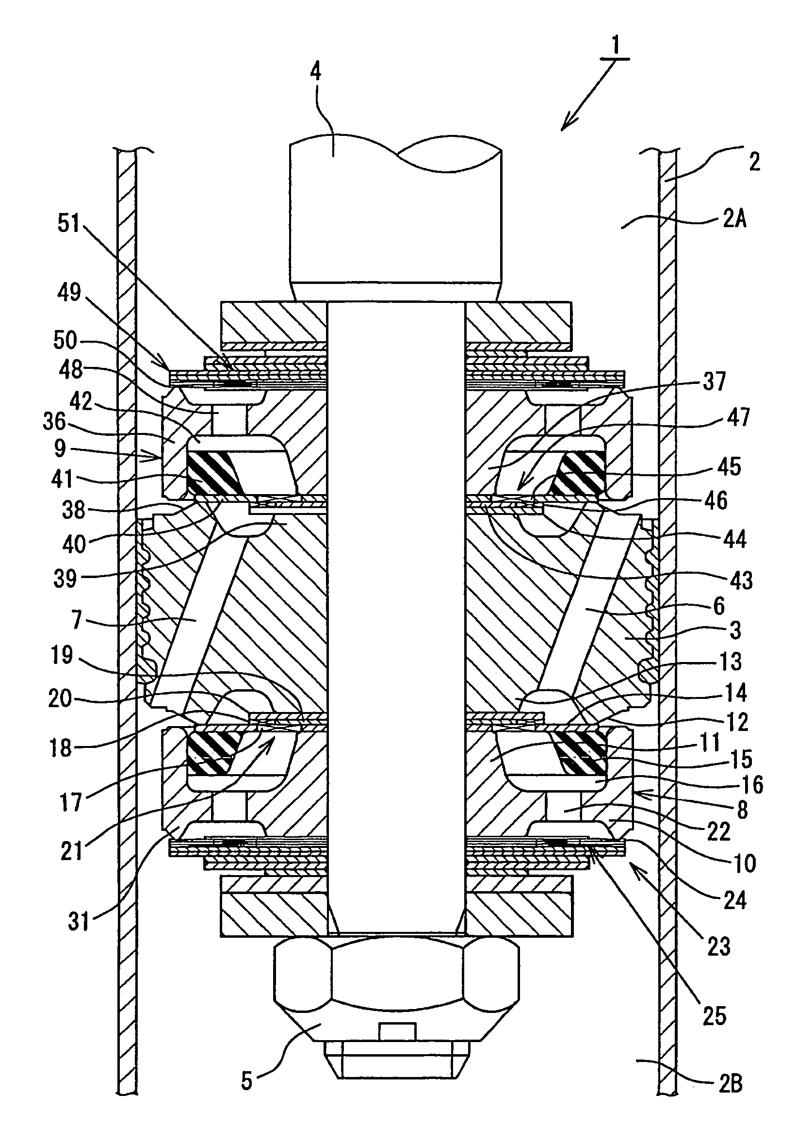
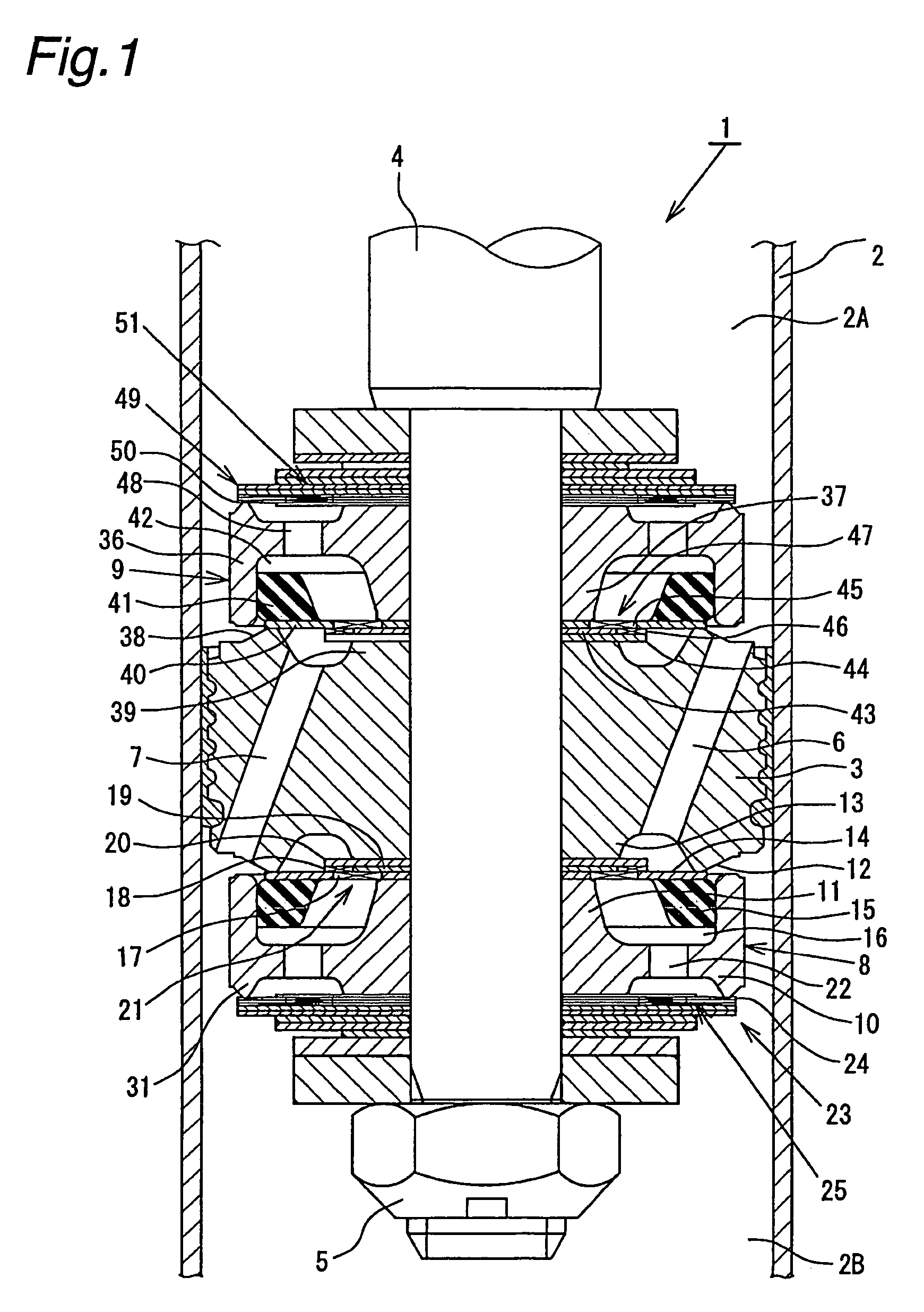
[0038]Hereinbelow, an embodiment of the present invention is described in detail, referring to the drawings.

[0039]As indicated in FIGS. 1 and 2, a hydraulic shock absorber 1 according to this embodiment is a cylinder type hydraulic shock absorber adapted to be mounted on a suspension apparatus for a vehicle, such as an automobile. The hydraulic shock absorber 1 comprises a cylinder 2 (only a part of a side wall thereof is shown) in which a hydraulic fluid is sealably contained, and a piston 3 which is slidably fitted into the cylinder 2. By means of the piston 3, an inside of the cylinder 2 is divided into two chambers; namely, an upper cylinder chamber 2A and a lower cylinder chamber 2B. One end of a piston rod 4 is connected to the piston 3 by means of a nut 5. The other end of the piston rod 4 is inserted through a rod guide (not shown) and an oil seal (not shown) attached to an upper end portion of the cylinder 2, so as to extend to an outside of the cylinder. The lower cylinder...


PUM


Abstract

A piston connected to a piston rod is fitted into a cylinder in which a hydraulic fluid is sealably contained. A flow of the hydraulic fluid is generated in an extension-side fluid passage and a compression-side fluid passage according to a sliding motion of the piston, and this flow of the hydraulic fluid is controlled by a main disk valve, to thereby generate a damping force. A valve-opening pressure of the main disk valve is controlled by an internal pressure of a back-pressure chamber generated due to a difference in flow path area between a back-pressure chamber inlet fluid passage and a downstream-side orifice. During a reverse stroke, a check valve is opened, to thereby introduce a pressure in a downstream-side cylinder chamber into the back-pressure chamber, so that the main disk valve can be maintained in a closed position and a stable damping force can be generated.

Description

BACKGROUND OF THE INVENTION[0001]The present invention relates to a hydraulic shock absorber which is suitably mounted on a suspension apparatus for a vehicle, such as an automobile.[0002]Generally, a cylinder-type hydraulic shock absorber mounted on a suspension apparatus for a vehicle, such as an automobile, comprises: a cylinder in which a hydraulic fluid is sealably contained; a piston portion which is slidably fitted into the cylinder and connected to a piston rod; and a damping force generating mechanism provided in the piston portion. The damping force generating mechanism includes a hydraulic fluid passage, an orifice, a disk valve, etc. In the damping force generating mechanism, a flow of hydraulic fluid in the hydraulic fluid passage, which is generated due to a sliding motion of the piston in the cylinder according to a stroke of the piston rod, is controlled by means of the orifice and the disk valve, to thereby generate a damping force. In a low-speed region of the pist...

Claims


Application Information

Patent Timeline
Patent Type & Authority Patents(United States)
IPC IPC(8): F16F9/34F16F9/50F16F9/348
CPCF16F9/348
Inventor YAMAGUCHI, HIROYUKI
Owner HITACHI ASTEMO LTD
Why Eureka
Try Eureka