Multifunctional illumination device

a multi-functional, illumination device technology, applied in lighting support devices, lighting and heating apparatuses, instruments, etc., can solve problems such as restricted variability in the design of possible beam paths

Active Publication Date: 2008-01-29
CHEMTRON RES
View PDF12 Cites 6 Cited by
  • Summary
  • Abstract
  • Description
  • Claims
  • Application Information

AI Technical Summary

Benefits of technology

[0010]Starting from the prior art, it is the object of the invention to provide a multifunctional illumination device that can be implemented in a compact design and in the case of which the path of radiation of the illumination and sensor device can be freely determined in a very wide range.
[0011]The solution within the scope of the first embodiment of the invention provides that the luminous means of the illumination device are formed by an arrangement of a multiplicity of semiconductor light sources grouped to form an array, and that sensor elements are arranged instead of the semiconductor light sources at individual positions of this array. It is thereby possible to provide advantageously a multifunctional headlamp that can be implemented in a robust design as a compact unit in a very small space. Since the light sources and the sensor elements no longer need to necessarily use the same optical system, but each individual element of the multifunctional headlamp can have an individually fashioned optical system, the beam path of the illumination device can be separated from the field of view of the sensors, and can be fixed independently of one another within wide ranges.
[0015]In order to implement a design of the multifunctional illumination device that is as compact as possible, the individual optics that are assigned to the semiconductor light sources or the individual sensors are designed to be as flat as possible and have as small a cross-sectional surface as possible on the side where they are connected to the semiconductor light sources or sensors. Thus, it is possible to achieve a packing density of optical and sensor elements that simultaneously permits a high radiation density and a high sensor sensitivity. In particular, the radiation density and the sensitivity can thereby be raised for specific applications when these applications are not implemented with the aid of individual elements, but when a number of elements (semiconductor light sources or sensors) are interconnected for this purpose to form groups. This grouping can both be performed permanently, for example by hard-wiring, or else be fashioned flexibly within the context of targeted control and selection.

Problems solved by technology

If, nevertheless, the aim is to implement a spatially compact design, this is possible only with the aid of delicate mirror arrangements that can also be severely damaged even in the event of trivial accidents of no importance occurring in road traffic.
However, the compact, robust design results here in a restricted variability in the design of the possible beam paths.

Method used


Image

  • Multifunctional illumination device
  • Multifunctional illumination device

Examples


Embodiment Construction

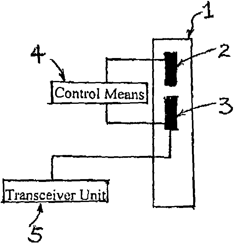
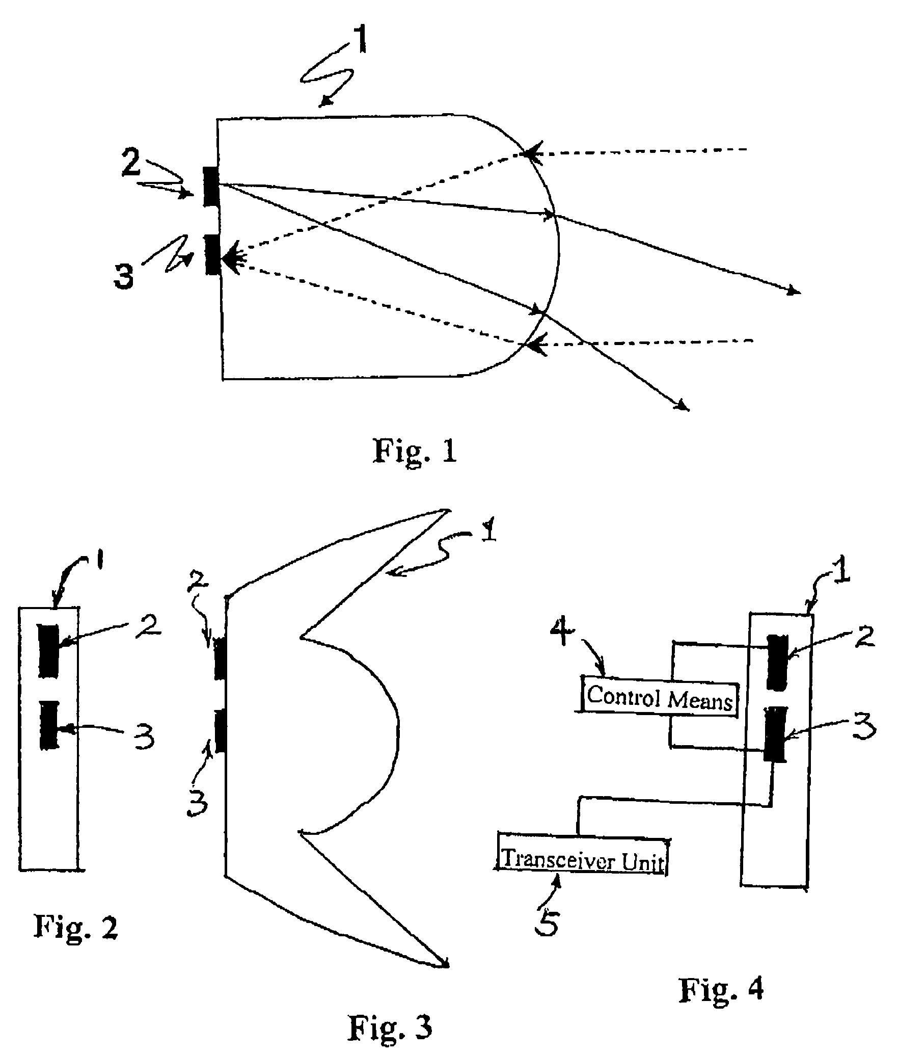
[0021]The multifunctional illumination device can be fashioned in a particularly advantageous and compact way aimed at efficiency by assigning at least individual optical systems a number of semiconductor light sources or sensor elements. In such a case, one optical system acts on the individual light sources and sensors in a different way such that these exhibit different emission characteristics and reception characteristics. In practice, this can frequently be utilized extremely advantageously, for example by positioning a semiconductor light source at an optical system such that when functioning as a lower beam it illuminates the area right in front of a vehicle, while the sensor is positioned at the optical system such that can detect signals from regions further away in front of the vehicle. Such an arrangement is shown by way of example in a diagrammatic illustration of FIG. 1 relating to this application. FIG. 1 shows the cross section of an optical system (1) that is genera...


PUM


Abstract

An illumination device has an illumination means formed by an arrangement of a plurality of semiconductor light sources (2) grouped together to form a field. Sensor elements (3) are arranged at individual positions of the field instead of the semiconductor sources (2). A multifunctional headlight can thus be advantageously created. The headlight can be embodied as a robust, compact, low-space unit. By virtue of the fact that the light sources (2) and the sensor elements (3) do not necessarily use the same lens system (1) i.e. each individual element of the multifunctional headlight can be provided with an individually designed lens system (1), the beam path of the illumination device can be separated from the field of vision of the sensor system and can thus be determined independently over large areas.

Description

[0001]This application is a national stage of PCT / EP2003 / 013917 filed Dec. 9, 2003 and based upon DE 102 59 185.7 filed Dec. 18, 2002 under the International Convention.BACKGROUND OF THE INVENTION[0002]1. Field of the Invention[0003]The invention relates to a multifunctional illumination device and a method for operating such a device.[0004]2. Related Art of the Invention[0005]For the purpose of improving safety in road traffic, in addition to conventional illumination equipment modern vehicles have additional sensor systems, which directly or indirectly support the vehicle driver and are intended for observing the surroundings of the vehicle, particularly with regard to the early detection of dangerous situations. These include, in particular, radar systems for detecting the range and relative speed of objects, or else night vision improvement systems that are based on the illumination of the road surroundings with infrared light. These systems are generally designed as independent...

Claims


Application Information

Patent Timeline
Patent Type & Authority Patents(United States)
IPC IPC(8): B60Q1/00B60Q1/04G01S7/481
CPCB60Q1/0023B60Q1/04B60Q9/006G01S7/481
Inventor GRIESINGER, MANFREDHARTLIEB, MARKUSKINCES, WILHELMLEIS, HANS-GEORGROTHE, SIEGFRIED
Owner CHEMTRON RES
Why Eureka
Try Eureka