Steering coupler

a technology of coupling and steering wheel, applied in the direction of couplings, slip couplings, transportation and packaging, etc., can solve the problems of driver losing control of the vehicle at least temporarily, wheel contains enough energy to injure the driver, and the steering wheel to rotate violently, so as to reduce the rotational force felt

Inactive Publication Date: 2008-01-29
WALLER CHARLES L
View PDF6 Cites 4 Cited by
  • Summary
  • Abstract
  • Description
  • Claims
  • Application Information

AI Technical Summary

Benefits of technology

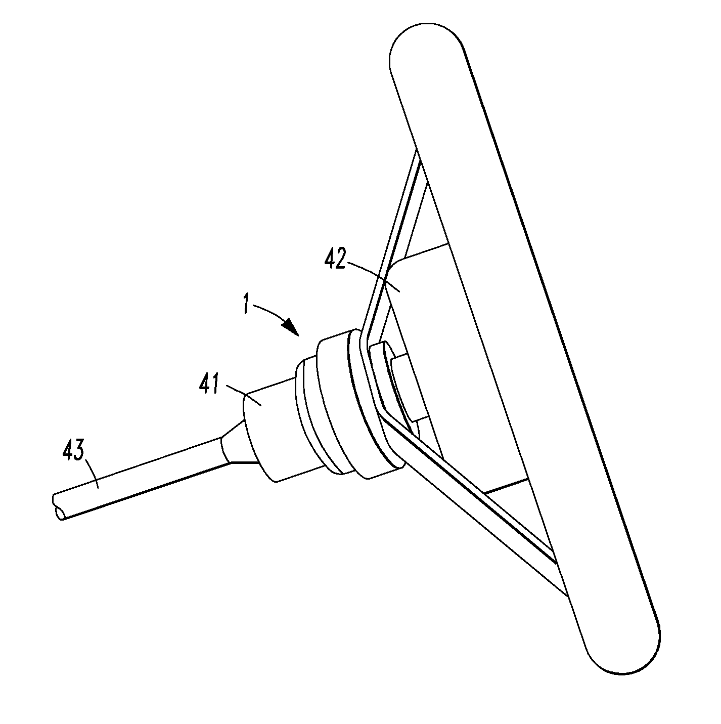
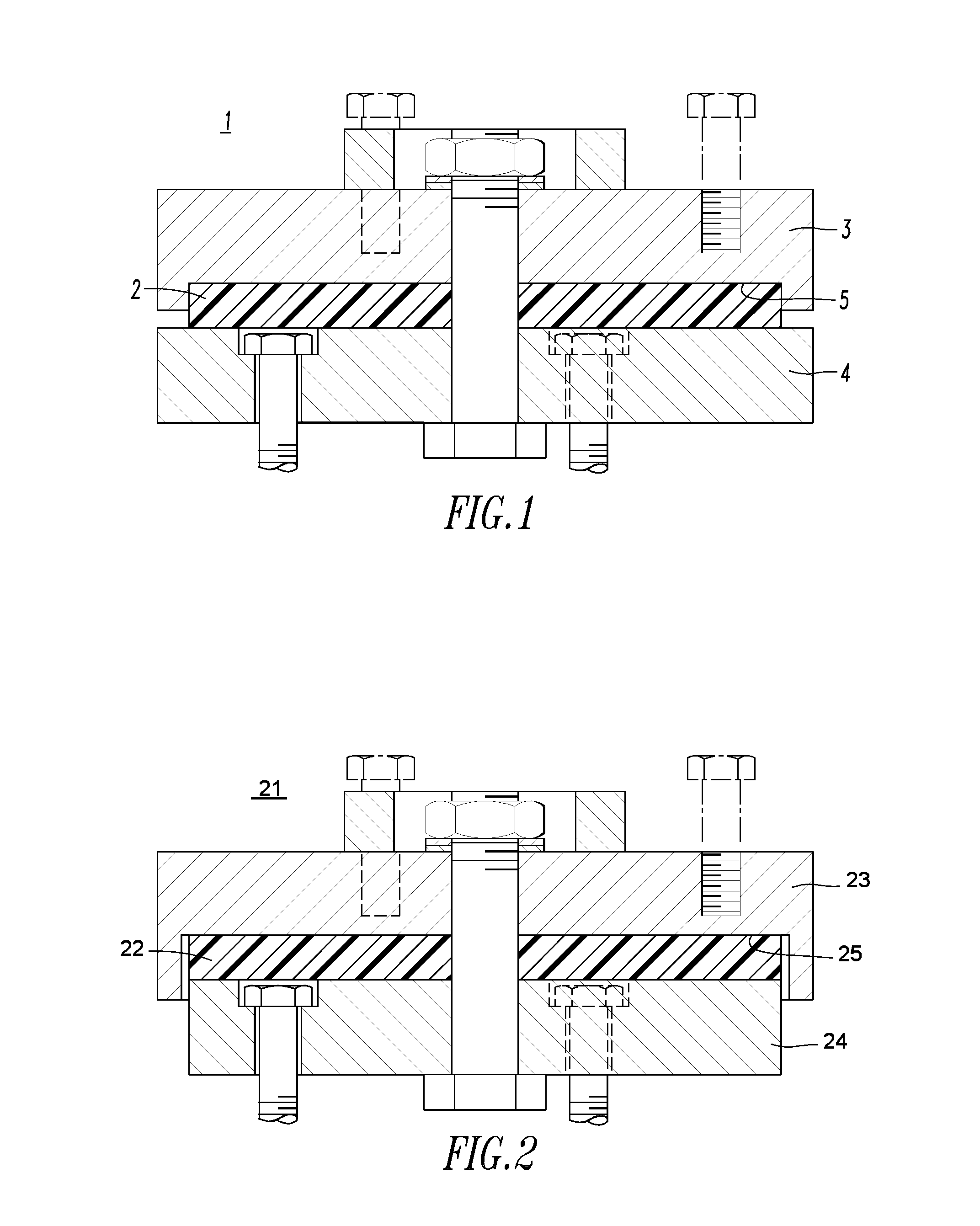
[0008]The present invention relates to a coupling that reduces the rotational force felt by a driver should the wheels impact an obstacle. The coupling is particularly suited for vehicles comprising simple, single-unit steering assemblies.
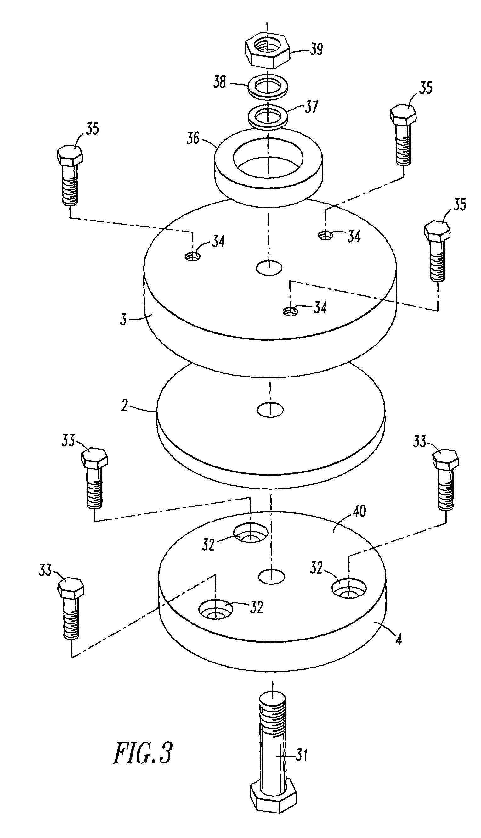
[0009]The coupling permits a certain amount of slippage between the wheels and the steering wheel without a total loss of steering. The driver may set a threshold torque at which slippage occurs, thereby controlling the “feel” of the steering.
[0011]The threshold torque may be exceeded, for example, when the wheels impact an obstruction that causes a torque above the threshold. The coupling prevents torque above the threshold from passing to the steering wheel. Injury to the driver can be avoided. Steering feel is retained. Once the obstruction is passed, full steering control can be regained.

Problems solved by technology

The wheels impacting a curb or other obstruction at high speed can cause the steering wheel to rotate violently.
A sudden violent rotation of the steering wheel contains enough energy to injure the driver.
Even if the driver escapes injury, the sudden movement of the steering wheel can cause the driver to lose control of the vehicle at least temporarily.
Power steering systems add significant complexity and weight to the steering system and reduce, but do not eliminate, the risk.
Electronic systems can be effective, but are expensive, difficult to install, and subject to breakdown.
Unfortunately, this leads to at least a temporary loss in steering control.

Method used


Image

  • Steering coupler
  • Steering coupler
  • Steering coupler

Examples


example 1

[0026]Before the beginning of a race, a driver installed a steering coupler of the present invention on a car. Nearing the end of the race, the driver attempted to pass the leader on the inside of the track. The track included grader tires on the inside radius of the track. At high speed, the left front wheel of the car hit one of the grader tires. The impact tore the wheel spindle and brake assembly from the car. Only the yellow caution light alerted the driver to the damage to his car. Inspection revealed the steering coupler rotated more than 180 degrees. The driver suffered no injury. In contrast, without the steering coupler of the present invention, an accident of this type would likely have seriously injured the driver's wrists or hands.

example 2

[0027]A driver entered a race in a car equipped with the steering coupler of the present invention. The driver noticed a disabled car and attempted to avoid it. This caused his car to go into a spin. A third car collided with the driver's right front wheel. The driver went to the pit with what he thought was a flat tire. To his amazement, he found every bar on the right front steering assembly either broken or bent. The steering coupler had rotated 180 degrees, but the driver was not injured.

example 3

[0028]During a race, a first car having a steering coupler of the present invention spun out on a turn. A second car hit the first car on the left front tire. The driver of the first car managed to regain control and win the race. Post-race inspection revealed a bent spindle tie rod, helm joints and bars on the left wheel. The steering coupler had rotated about 90 degrees. The driver suffered no injury.


PUM


Abstract

A steering coupling reduces the rotational force felt by a driver should the wheels impact an obstacle. The coupling is particularly suited for vehicles comprising simple, single-unit steering assemblies. The coupling permits a certain amount of slippage between the wheels and the steering wheel without a total loss of steering. The driver may set a threshold torque at which slippage occurs, thereby controlling the “feel” of the steering. The coupling includes a friction disc that permits rotational movement between two housings in the steering assembly.

Description

[0001]The present application claims priority to U.S. 60 / 603,986, filed 24 Aug. 2004.FIELD OF THE INVENTION[0002]The present invention is directed to a steering coupling and is especially adapted for motor vehicles having a single unit steering system.BACKGROUND OF THE INVENTION[0003]Steering systems of certain motor vehicles, such as racecars, demolition derby cars and off-road vehicles, include a direct link between a steering wheel and wheels. The steering wheel is rigidly secured to a steering column. The steering column is connected to a mechanism that translates rotational motion of the steering wheel into a turning motion of the wheels. In one embodiment, the mechanism includes tie rods attach directly to the steering column. Each tie rod is connected to one of the wheels. Turning the steering wheel rotates the steering column and translates the tie rods in opposite directions, thereby moving the wheels in the intended direction.[0004]Advantageously, this system is simple, in...

Claims


Application Information

Patent Timeline
Patent Type & Authority Patents(United States)
IPC IPC(8): F16D7/02
CPCB62D1/16B62D7/224F16D7/024
Inventor WALLER, CHARLES L.
Owner WALLER CHARLES L
Why Eureka
Try Eureka