Direct discharging sealing system of closestool

A sealing system and toilet technology, applied in the field of sanitary ware, can solve the problems of wasting water resources, high blockage rate, influence, etc., and achieve the effects of reducing failures, isolating bacteria sources, and reducing rotational force

Inactive Publication Date: 2011-09-21
汤炳生
View PDF4 Cites 2 Cited by
  • Summary
  • Abstract
  • Description
  • Claims
  • Application Information

AI Technical Summary

Problems solved by technology

[0002] In order to prevent the leakage of peculiar smell, the existing toilets all adopt the S-shaped curve to implement the water sealing method, but this water sealing method must use more than 6L of water source, and the sewage is carried and returned to the net in a fluid manner. The way of sewage discharge is the key to determining the water consumption and causing failures, and there is a high clogging rate in general, and it often takes several flushes to eliminate the failure. The toilet is made of ceramics, and the inner wall of the S-shaped curve cannot be guaranteed during the manufacturing process. It is smooth and glazed. For this reason, the existing sewage discharge method of the S-shaped curve determines that the toilet has become the main water-consuming part in human daily life. Using the above-mentioned method to prevent the leakage of peculiar smell will not only waste water resources, but also cannot completely Eliminate odors that affect the home and other environments

Method used


Image

  • Direct discharging sealing system of closestool
  • Direct discharging sealing system of closestool
  • Direct discharging sealing system of closestool

Examples


Embodiment Construction

[0011] In order to deepen the understanding of the present invention, the present invention will be further described below in conjunction with the embodiments and accompanying drawings. The embodiments are only used to explain the present invention and do not constitute a limitation to the protection scope of the present invention.

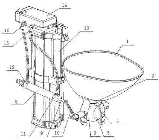
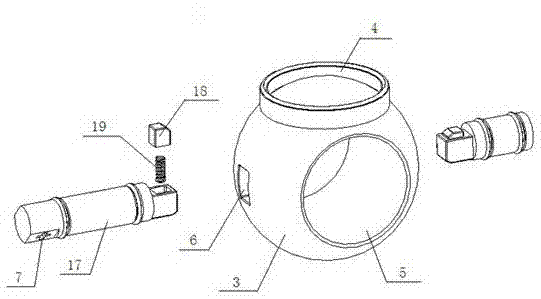
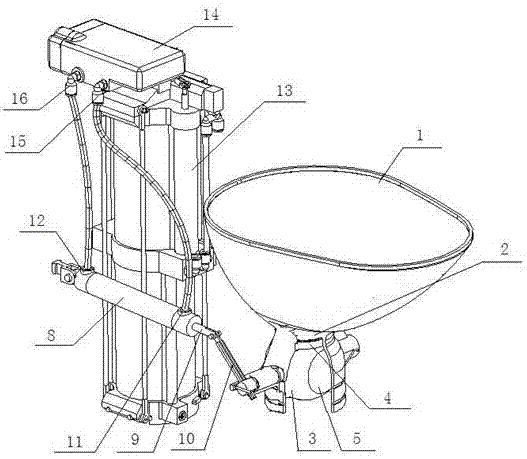
[0012] like figure 1 and figure 2 Shows a specific implementation of the toilet straight row sealing system of the present invention, including a toilet collector 1, a ball valve 3 is provided in the lower neck of the cavity neck 2 of the toilet collector 1, and a seal is provided between the ball valve 3 and the cavity neck 2 ring and sealing ring 4, the ball valve 3 is provided with a drain hole 5, and two rectangular blind holes 6 are symmetrically arranged on the middle side wall of the ball valve 3, and one end of the central shaft group is connected to the two blind holes 6, and two The other end of the central shaft group passes through ...


PUM


Abstract

The invention discloses a direct discharging sealing system of a closestool. The system comprises a toilet waste collector, wherein a ball valve is arranged in the lower neck of a cavity neck of the toilet waste collector; the ball valve is provided with a discharge hole; two blind holes are symmetrically arranged on the side walls of the ball valve; one ends of two central shaft assemblies are connected in the two blind holes; the other ends of the two central shaft assemblies penetrate through the cavity neck of the toilet waste collector; the end of any one central shaft assembly, which is arranged outside the cavity neck, is provided with a rod through hole; a first power cylinder is arranged at one side of the toilet waste collector; one end of a piston rod in the first power cylinder goes out of the first power cylinder and is connected with one end of a connecting rod; the other end of the connecting rod is inserted into the rod through hole; a front pipe connector and a rear pipe connector are arranged on the upper surface of the first power cylinder; a second power cylinder device is arranged at the rear part of the toilet waste collector; a time delay unit is connected with the upper surface of the second power cylinder device; a front connector and a rear connector are arranged on the lower part of the side wall of the time delay unit; the front connector and the front pipe connector are connected by a pipeline; and the rear connector and the rear pipe connector are connected by a pipeline. The system has the advantages of high efficiency, water saving, low fault rate and pathogen source isolation.

Description

technical field [0001] The invention relates to a sanitary appliance, in particular to a straight-line sealing system for a toilet. Background technique [0002] In order to prevent the leakage of peculiar smell, the existing toilets all adopt the S-shaped curve to implement the water sealing method, but this water sealing method must use more than 6L of water source, and the sewage is carried and returned to the net in a fluid manner. The way of sewage discharge is the key to determining the water consumption and causing failures, and there is a high clogging rate in general, and it often takes several flushes to eliminate the failure. The toilet is made of ceramics, and the inner wall of the S-shaped curve cannot be guaranteed during the manufacturing process. It is smooth and glazed. For this reason, the existing sewage discharge method of the S-shaped curve determines that the toilet has become the main water-consuming part in human daily life. Using the above-mentioned ...

Claims


Application Information

Patent Timeline
Patent Type & Authority Applications(China)
IPC IPC(8): E03D5/012E03D11/10E03D3/02E03D3/04
Inventor 汤炳生
Owner 汤炳生
Why Eureka
Try Eureka