Connector

a technology of connectors and connector parts, applied in the direction of flexible/turnable line connectors, coupling device connections, coupling parts engagement/disengagement, etc., can solve the problem of not increasing the work process, and achieve the effect of preventing the connection, reducing the rotation force at the peak, and reducing the body siz

Active Publication Date: 2015-08-06
YAZAKI CORP
View PDF5 Cites 2 Cited by
  • Summary
  • Abstract
  • Description
  • Claims
  • Application Information

AI Technical Summary

Benefits of technology

[0014]According to another aspect of the present invention, provided is a connector in which distances from a center axis of the first terminal to the second terminals are different from each other. This provides a structure in which each of the second terminals can contact only the individually corresponding contact portion (second contact portions), respectively, so that if it is tried to connect the second terminals and the contact portions in wrong combination, the connection is prevented. Consequently, mis-contact therebetween can be prevented in a reliable manner.
[0015]According to another aspect of the present invention, provided is a connector in which the second terminals are opposed to each other in a pair across the first terminal, the fitting grooves are formed in a pair corresponding to the pair of second terminals, and a distance from a rotation start position of one of the second terminals to a fitting start position of the one of the second terminals fitting in one of the fitting grooves and a distance from a rotation start position of the other second terminal to a fitting start position of the other second terminal fitting in the other fitting groove are different from each other. Accordingly, the time at which the one of the second terminals enters the one of the fitting grooves (the fitting start timing) and the time at which the other second terminal enters the other fitting groove (the fitting start timing) can be shifted, so that the timings at which they enter (the fitting start timings) do not coincide with each other. Consequently, the peak of the rotation force during the relative rotation of the male-side housing and the female-side housing for their engagement can be distributed, so that the rotation force at the peak can be reduced.
[0016]According to the present invention, it is possible to provide a connector that can downsize its body and can reduce terminal connecting workload.

Problems solved by technology

Moreover, in connecting the terminals and the contact portions, for example, fastening work using bolts and nuts is unnecessary, the work process is not increased, and it is also unnecessary to provide an opening or the like for inserting a work tool or the like into the connector.

Method used


Image

  • Connector
  • Connector
  • Connector

Examples


first embodiment

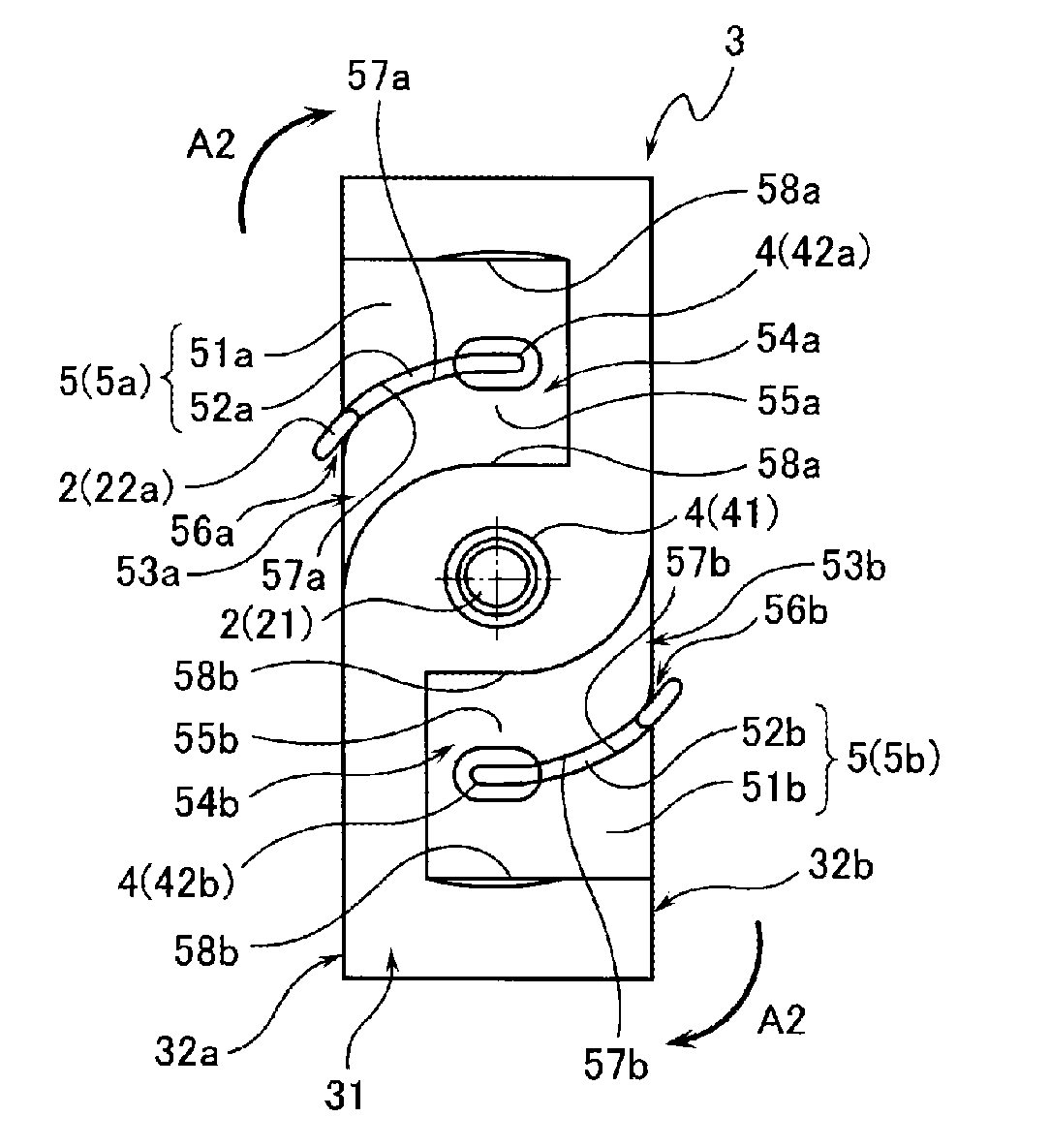
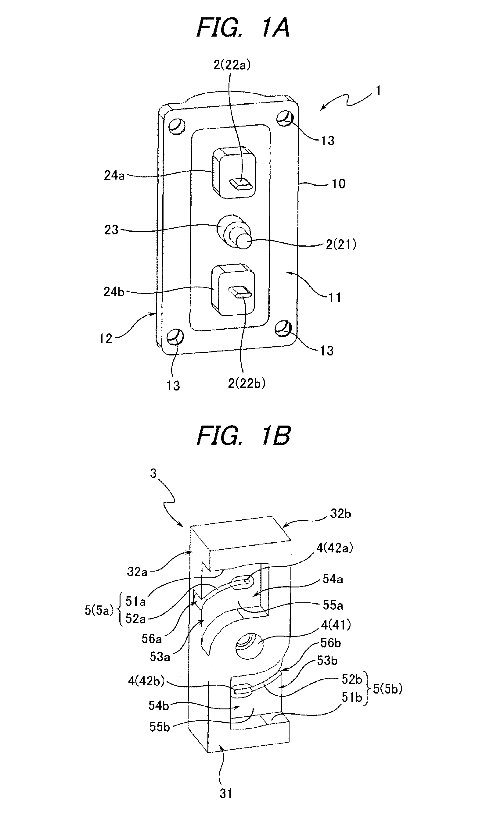
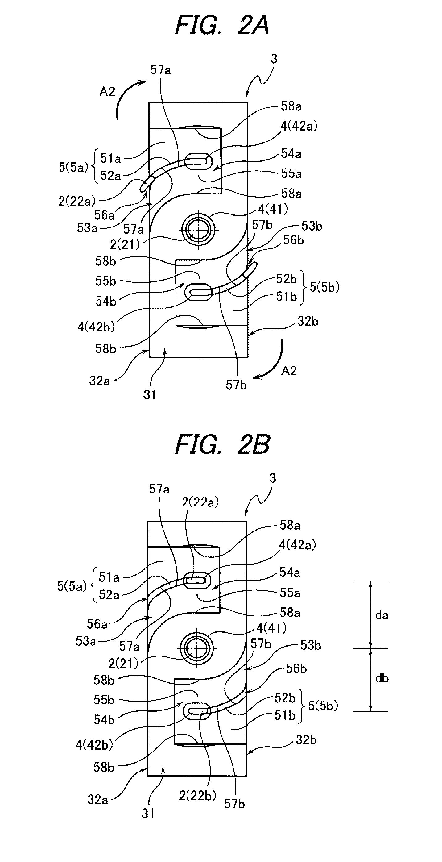
[0020]Hereinafter, a connector according to the present invention will be described with reference to the attached drawings. FIGS. 1A and 1B are views showing an overall structure of a connector according to an embodiment of the present invention, FIG. 1A being a perspective view showing a structure of one connector housing (a male-side housing) forming a pair, and FIG. 1B being a perspective view showing a structure of the other connector housing (a female-side housing). FIGS. 2A and 2B are views schematically showing a rotation of terminals (second terminals which will be described later) when engaging a male-side housing and a female-side housing of the connector according to a first embodiment of the present invention, FIG. 2A being a schematic view showing a state at the time of starting the rotation, and FIG. 2B being a schematic view showing a state at the time when the rotation is stopped (when the terminals have been connected).

[0021]As shown in FIG. 1, the connector has th...

second embodiment

[0042]In the connector according to the first embodiment described above (FIGS. 1A to 2B), when the male-side housing 1 and the female-side housing 3 are rotated relative to each other and engaged with each other, the fitting of the second terminal 22a in the second contact portion 42a and the fitting of the second terminal 22b in the second contact portion 42b, in other words, the entrance of the second terminal 22a into the terminal fitting groove 52a and the entrance of the second terminal 22b into the terminal fitting groove 52b are synchronized (occur at the same timing). In other words, the distance from the rotation start position of the second terminal 22a to the fitting start position of the second terminal 22a fitting in the terminal fitting groove 52a and the distance from the rotation start position of the second terminal 22b to the fitting start position of the second terminal 22b fitting in the terminal fitting groove 52b of the second terminal 22b are set to be equal ...


PUM


Abstract

A connector has a male-side housing provided with terminals and a female-side housing provided with contact portions to contact the terminals. In a state in which the male-side housing and the female-side housing are rotated relative to each other and engaged with each other, the terminals and the contact portions are contact each other to be electrically connected.

Description

CROSS REFERENCE TO RELATED APPLICATIONS[0001]This application is a continuation of International Patent Application No. PCT / JP2013 / 080088 filed on Nov. 7, 2013, claiming priority from Japanese Patent Application No. 2012-245646 filed on Nov. 7, 2012, the contents of which are incorporated herein by reference.FIELD OF INVENTION[0002]The present invention relates to the structure of a connector for connecting a terminal.BACKGROUND ART[0003]In vehicles such as cars, various kinds of connectors for connecting terminals are used to connect an electric circuit formed between in-vehicle electric components (see Patent Document 1 and Patent Document 2).[0004]Patent Document 1 discloses a structure example of a connector where a member holding female terminals (female terminal housing) and a member holding male terminals (male terminal housing) to be connected to the female terminals are configured as separate members. In such a connector, when connecting the female terminals and the male te...

Claims


Application Information

Patent Timeline
Patent Type & Authority Applications(United States)
IPC IPC(8): H01R13/631H01R35/04
CPCH01R13/62H01R13/71H01R35/04H01R13/631H01R13/629H01R2201/26H01R2105/00
Inventor KATO, HAJIMENAKAMURA, MIKIOHMORI, YOSHITAKE
Owner YAZAKI CORP
Why Eureka
Try Eureka