Implantable microphone having sensitivity and frequency response

a microphone and frequency response technology, applied in the field of implantable microphone devices, can solve the problems of reducing the acoustic compliance of the sealed air cavity, and achieve the effects of reducing the overall component count, reducing the volume of the air cavity, and reducing the acoustic compliance of the microphon

Inactive Publication Date: 2008-01-29
MED EL ELEKTROMEDIZINISCHE GERAETE GMBH
View PDF28 Cites 89 Cited by
  • Summary
  • Abstract
  • Description
  • Claims
  • Application Information

AI Technical Summary

Benefits of technology

[0010]The present invention provides implantable microphone devices that may be utilized in hearing systems, particularly in systems having bone mounted and other implantable drivers. The device comprises a flexible membrane disposed over a sealed cavity. The membrane may be made substantially flexible by etching or forming the membrane until it is very thin. Also, the sealed cavity may be limited to a very small volume which decreases the sealed air cavity acoustic compliance. Both of these examples simultaneously increase overall sensitivity of the device and move the damped resonance peak to higher frequencies.
[0014]In a second aspect of the implantable microphone device, surface details are positioned on a surface of the housing. Preferably, the surface details may include pits, grooves, or at least one hole which connects the primary air cavity to a rear chamber of the housing. The surface details are provided to increase resonance peak damping.
[0016]In a fourth aspect, the implantable microphone device, comprises a biocompatible material positioned proximate to the membrane. Preferably, the biocompatible material is biodegradable and degrades over time. Example materials include lactide and glycolide polymers. The position of the biocompatible material may vary from, for example, simple contact with only the front surface of the membrane to complete encapsulation of the entire microphone. This material provides protection from initial tissue growth on the microphone which may occur after implantation of the device. A volume occupying layer may be used to occupy a space between the membrane and an opposing surface of the biocompatible material. The volume occupying layer may naturally, over time, permanently fill up with body fluids or may comprise a permanent, biocompatible fluid-filled sack. In either form, these fluids will maintain an interface between the membrane and the surrounding tissue.
[0017]In a fifth aspect, the implantable microphone device comprises a microphone assembly with the secondary air cavity removed such that the electret membrane is directly exposed to the primary air cavity. The removal of the secondary air cavity creates a further reduction in overall air cavity volume which leads to a reduction in the acoustic compliance of the microphone.
[0018]In a sixth aspect, the implantable microphone device has a modified microphone assembly which eliminates the electret membrane. The assembly comprises an insulation layer secured on the inside surface of the implantable microphone membrane. An electret membrane-type material is, in turn, secured on the insulation layer. A backplate is disposed within the primary air cavity proximate to the insulation / membrane-type material combination. This aspect of the invention provides the advantage of a direct electret displacement, a lower overall component count, and an overall thinner microphone profile.

Problems solved by technology

Also, the sealed cavity may be limited to a very small volume which decreases the sealed air cavity acoustic compliance.

Method used


Image

  • Implantable microphone having sensitivity and frequency response
  • Implantable microphone having sensitivity and frequency response
  • Implantable microphone having sensitivity and frequency response

Examples


Embodiment Construction

[0030]In the description that follows, the present invention will be described in reference to hearing systems. The present invention, however, is not limited to any use or configuration. Therefore, the description the embodiments that follow is for purposes of illustration and not limitation. The same reference numerals will be utilized to indicate structures corresponding to similar structures.

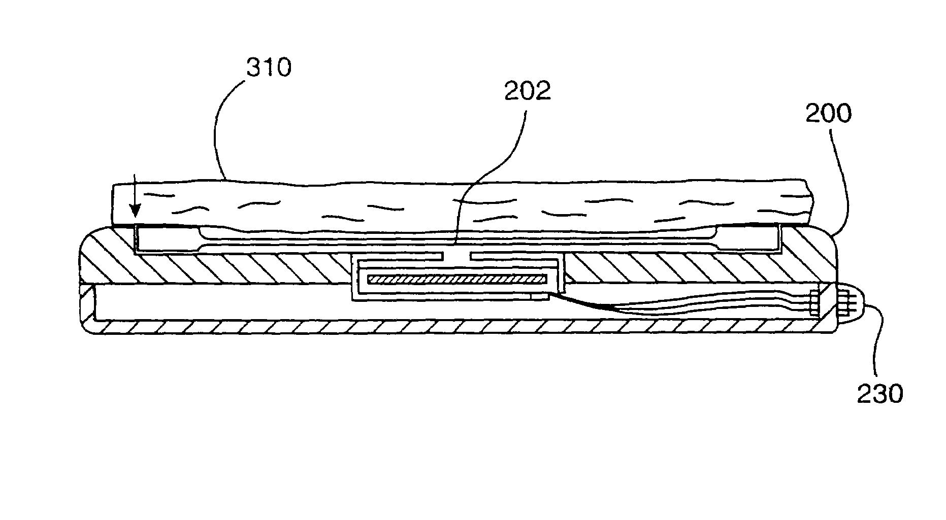
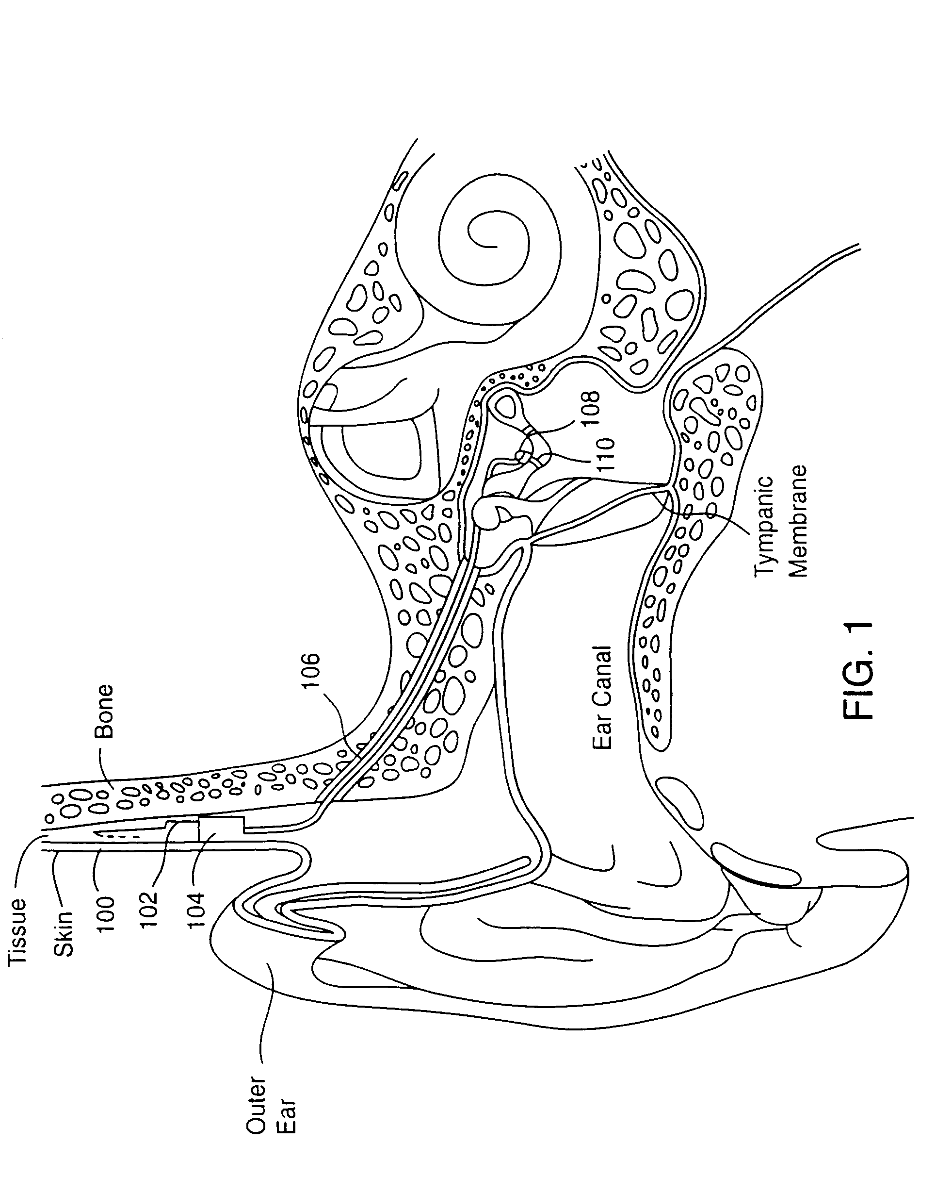
[0031]FIG. 1 illustrates an embodiment of the present invention in a hearing system. An implantable microphone 100 is located under the skin and tissue behind the outer ear or concha. The implantable microphone picks up sounds through the skin and tissue. The sounds are then translated into electrical signals and carried by leads 102 to a signal processor 104 which may also be located under skin and tissue.

[0032]The signal processor 104 receives the electrical signals from the implantable microphone 100 and processes the electrical signals appropriate for the hearing system and individual. A...


PUM


Abstract

Implantable microphone devices that may be utilized in hearing systems are provided. An implantable microphone device allows the implantable microphone's frequency response and sensitivity to be selected. A microphone device with an increased membrane flexibility and a decreased acoustic compliance of the sealed cavity. Vibrations of a membrane are transmitted through a primary air cavity and through an aperture of a microphone. Keeping a flexible membrane and decreasing the sealed air cavity compliance are the preferred way to simultaneously increase overall sensitivity of the device, and move the resonance peak to higher frequencies.

Description

CROSS-REFERENCES TO RELATED APPLICATIONS[0001]This application is a division of U.S. application Ser. No. 09 / 615,414, filed Jul. 12, 2000, now U.S. Pat. No. 6,626,822, which was a continuation of U.S. application Ser. No. 08 / 991,447, filed Dec. 16, 1997 (now U.S. Pat. No. 6,093,144), the full disclosures of which are incorporated herein by reference.BACKGROUND OF THE INVENTION[0002]The present invention is related to hearing systems and, more particularly, to implantable microphone devices that may be utilized in hearing systems.[0003]Conventional hearing aids are placed in the ear canal. However, these external devices have many inherent problems including the blockage of the normal avenue for hearing, discomfort because of the tight seal required to reduce the squeal from acoustic feedback and the all-too-common reluctance for hearing-impaired persons to wear a device that is visible.[0004]Recent advances in miniaturization have resulted in the development of hearing aids that can...

Claims


Application Information

Patent Timeline
Patent Type & Authority Patents(United States)
IPC IPC(8): H04R25/00H04R19/01
CPCH04R25/606H04R19/016H04R2225/67
Inventor JAEGER, ERIC M.BALL, GEOFFREY R.TUMLINSON, DUANE E.
Owner MED EL ELEKTROMEDIZINISCHE GERAETE GMBH
Why Eureka
Try Eureka