
Electronic beam steering for keyhole avoidance

a technology of electronic beam and keyhole avoidance, applied in the direction of antennas, instruments, movable bodies, etc., can solve the problems of not maintaining the required pointing accuracy in the vicinity, communication link could be temporarily lost, and the three-axis gimbaled control system could not accommodate the required antenna aperture to meet the desired antenna gain performan

Active Publication Date: 2008-01-29
THE BOEING CO
View PDF9 Cites 220 Cited by
  • Summary
  • Abstract
  • Description
  • Claims
  • Application Information

AI Technical Summary

Benefits of technology

The solution ensures reliable antenna pointing and signal strength in the keyhole region, maintaining less than 1 decibel signal loss across the field-of-regard, even at high elevation angles, without increasing antenna size or weight, thereby enhancing communication link reliability and efficiency.

Problems solved by technology

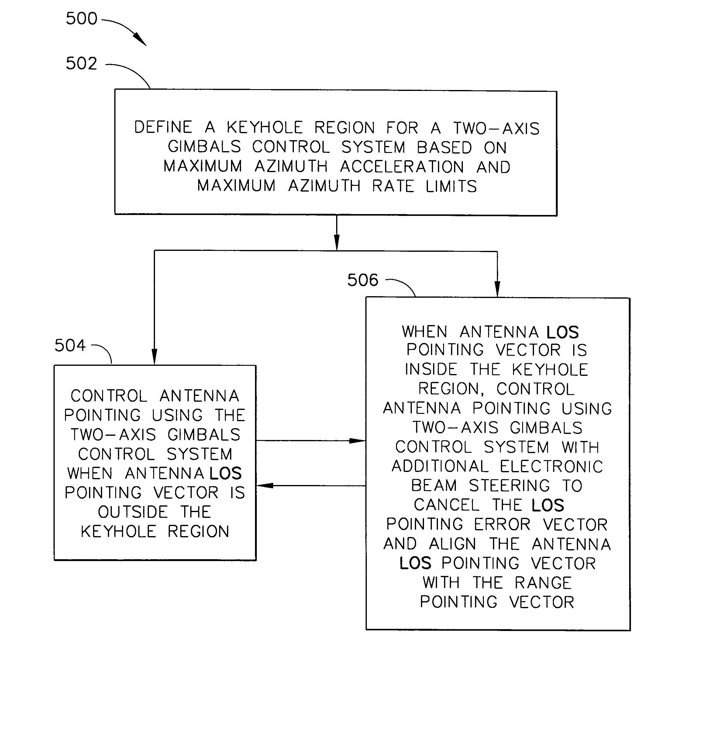
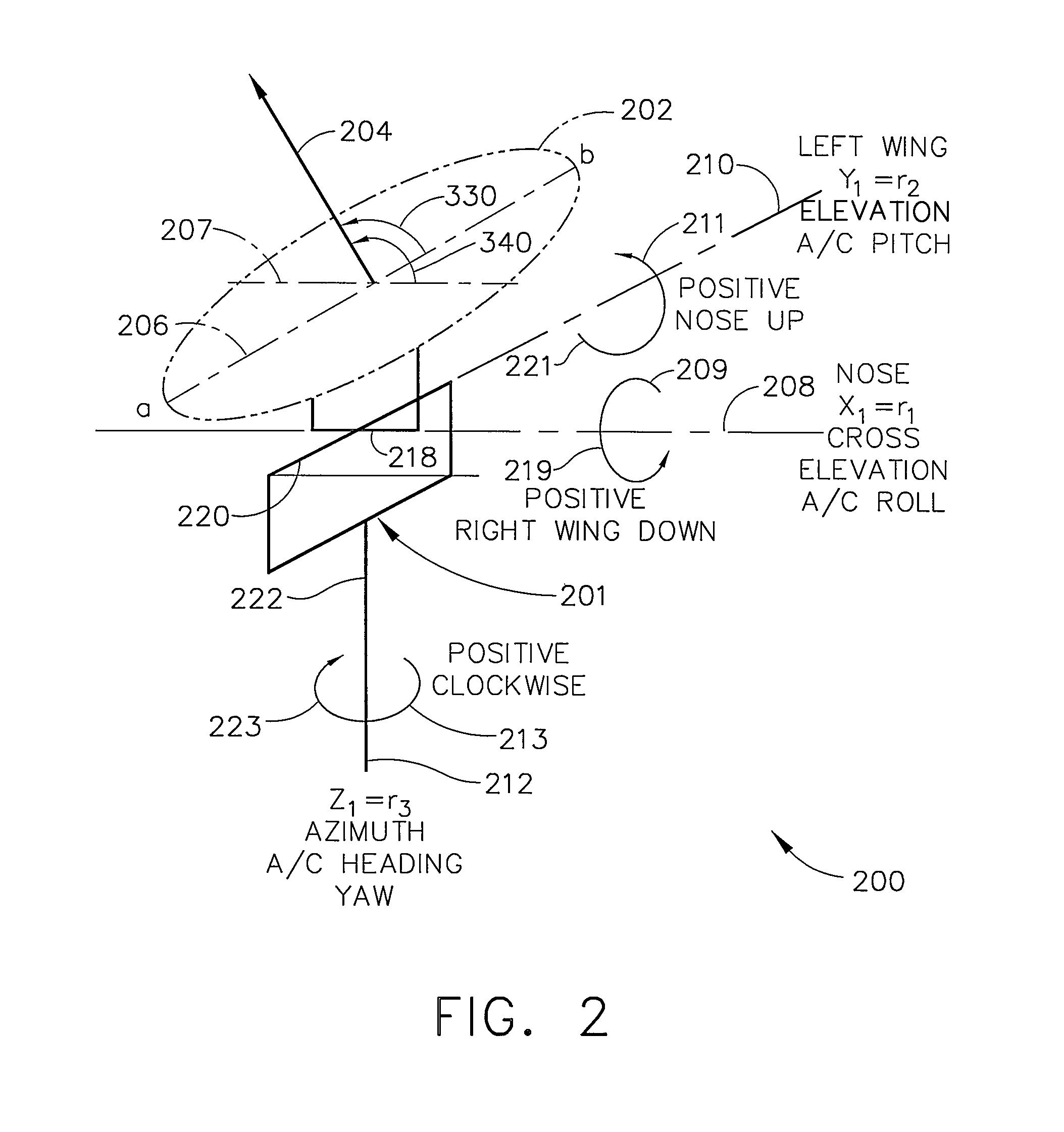
One prior art RF antenna designed for existing EHF communication terminals used a two-axis gimbaled control system, which could not maintain the required pointing accuracy in the vicinity of the keyhole region—the region where the antenna pointing elevation angle is close to 90 degrees.
Thus, in the keyhole region, the communication link could be temporarily lost due to pointing error using the two-axis gimbaled control system.
Because of the available antenna dome volume, however, the three-axis gimbaled control system could not accommodate the required antenna aperture to meet the desired antenna gain performance.

Method used


Image

  • Electronic beam steering for keyhole avoidance
  • Electronic beam steering for keyhole avoidance
  • Electronic beam steering for keyhole avoidance

Examples


Embodiment Construction

[0016]The following detailed description is of the best currently contemplated modes of carrying out the invention. The description is not to be taken in a limiting sense, but is made merely for the purpose of illustrating the general principles of the invention, since the scope of the invention is best defined by the appended claims.

[0017]Broadly, the present invention uses the electronically steered beams generated by a phased array antenna to add a third-axis motion for a two-axis gimbaled control system for antenna beam pointing from a moving platform for radio-frequency (RF) communication systems. For example, one embodiment is especially useful for antenna beam pointing in a beyond line-of-sight communications link between an aircraft and a satellite and provides reliable antenna pointing and signal strength in the keyhole region of the aircraft. One embodiment thus differs from prior art two-axis gimbals control systems—which do not provide reliable antenna pointing in the ke...


PUM


Abstract

An airborne radio frequency (RF) antenna terminal system includes a two-axis gimbals control system and a phased array antenna. The phased array antenna electronically steers the receive and transmit beams using phase shifters. The electronically steered beams provide a virtual third-axis for the two-axis gimbals control system. The combination of the electronically steered beams and the two-axis gimbaled system provides accurate beam steering for the keyhole region of the two-axis gimbals control system so that the RF communication link is prevented from being lost in the keyhole region.

Description

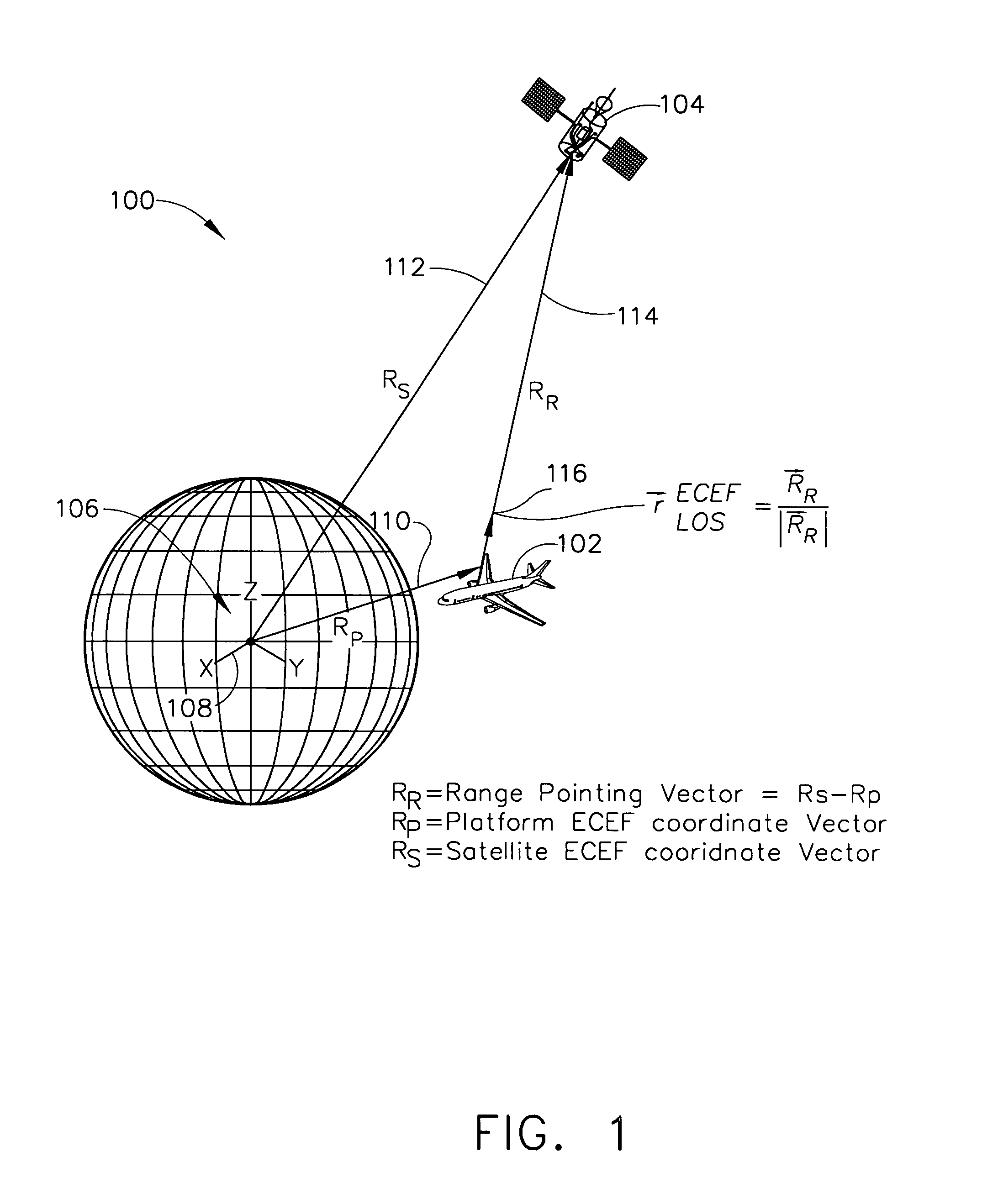
GOVERNMENT RIGHTS[0001]This invention was made with Government support under Contract Number: F19628-02-C-0048. The government has certain rights in this invention.BACKGROUND OF THE INVENTION[0002]The present invention generally relates to accurate beam pointing in the keyhole region of an airborne radio frequency (RF) antenna and, more particularly, to using phased array beam steering for third-axis motion in a two-axis gimbaled antenna control system.[0003]Airborne radio frequency (RF) antenna terminal systems have been developed for the FAB-T (Family of Advanced Beyond line-of-sight Terminal) program for military EHF (Extremely High Frequency) satellite communication systems. Such RF antenna terminal systems may, for example, be mounted on a moving platform—such as a B-52 aircraft—and are designed to acquire and track a geostationary satellite payload or a polar satellite payload to establish a two-way digital beyond line-of-sight communication service that is secure, jam-resista...

Claims


Application Information

Patent Timeline
Patent Type & Authority Patents(United States)
IPC IPC(8): H01Q3/00
CPCH01Q1/28H01Q3/16H01Q3/26
Inventor WU, YEONG-WEI ANDY
Owner THE BOEING CO
Learn More