Method of centerline generation in virtual objects

a technology of virtual objects and centerlines, applied in the field of 3d virtual environments, can solve the problems of not meeting the requirements of property 1, cannot be completely solved, computationally complex and expensive, etc., and achieve the effect of improving the speed of the second method and increasing processing speed

Inactive Publication Date: 2008-01-29
THE RES FOUND OF STATE UNIV OF NEW YORK
View PDF67 Cites 95 Cited by
  • Summary
  • Abstract
  • Description
  • Claims
  • Application Information

AI Technical Summary

Benefits of technology

[0016]A third method is a general method to improve the speed of the second method or any other method for centerline or skeleton computation that is based on having to examine all voxels in the object. The increased processing speed comes from obviating the need to evaluate all voxels in the object. Starting with an initial approximate centerline or skeleton, the centerline or skeleton computation method can be applied to a fake object that consists of just the centerline voxels and those very close to it, but still use the DFB values computed ones beforehand for the complete object. The resulting centerline / skeleton is an improvement over the initial one. The process can be iterated by using the result of the previous iteration as input to the next. Eventually this results in a centerline / skeleton that does not change any more which can then be used as final higher quality centerline / skeleton.

Problems solved by technology

Unfortunately, it does not satisfy property 1, because the shortest path tends to hug corners at high-curvature regions.
However, such efforts have not completely solved the problem, or involve distance function adjustment based on other measurements, and are computationally complex and expensive.
This technique satisfies properties 1 through 3 very well, but it does not satisfy property 4, due to the expensive processing iteration.

Method used


Image

  • Method of centerline generation in virtual objects
  • Method of centerline generation in virtual objects
  • Method of centerline generation in virtual objects

Examples


Embodiment Construction

[0022]The present invention will be described in the context of systems and methods for performing examination and navigation of virtual objects, such as in virtual colonoscopy procedures, but is not limited to such procedures. A system and method for performing such virtual examination and visualization of 3D virtual objects is described in U.S. Pat. No. 6,343,936, entitled “System and Method for Performing a Three-Dimensional Virtual Examination, Navigation and Visualization,” the disclosure of which is hereby incorporated by reference in its entirety. The present invention assumes that such systems and methods are used to acquire image data, create a three dimensional model of a virtual object and display the virtual object using a graphical user interface or other suitable user interface.

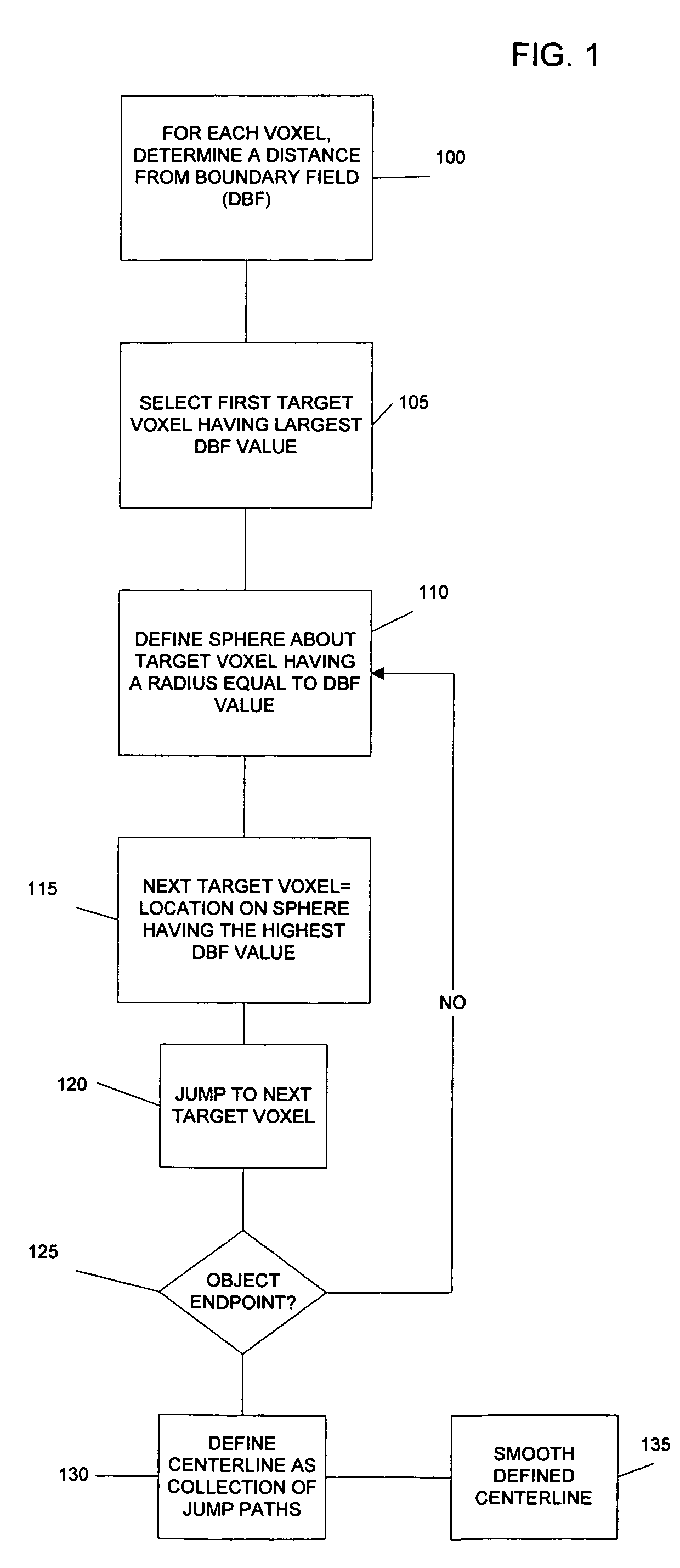
[0023]Referring to FIG. 1, a first method in accordance with the present invention determines the centerline through a virtual object based on a distance from boundary (DFB) field in which each ...


PUM


Abstract

Methods for generating a centerline or skeleton structure within a 3D virtual object are provided. A first method defines a centerline based on distance from boundary values along points of the defined centerline. A second method uses a distance from boundary field to assign costs to voxels in the virtual object and defines a minimum cost spanning tree based on assigned costs. The centerline is defined along the minimum cost spanning tree. Branches along the centerline are identified and added to the centerline to define a skeleton.

Description

RELATED APPLICATIONS[0001]This application claims the benefit of U.S. Provisional Application Ser. No. 60 / 322,046, entitled “Advanced Navigation and Detection for Virtual Examination,” which was filed on Sep. 14, 2001, the disclosure of which is hereby incorporated by reference in its entirety. This application may also be considered related to application Ser. No. 10 / 246,016, filed on Sep. 16, 2002 and entitled “System and Method for Navigating in Virtual Environments Using a Fluid Model” and to application Ser. No. 10 / 246,070 filed on Sep. 16, 2002, entitled “Computer Assisted Detection of Lesions Volumetric Medical Images.”[0002]Other co-pending applications which may be considered “related” to the present application include: Ser. No. 10 / 182,217, with a filing date of Feb. 19, 2003 and entitled “Computer Aided Treatment Planning;” Ser. No. 10 / 380,211, with a filing date of Feb. 2, 2004 and entitled “Centerline and Tree Branch Skeleton Determinator for Virtual Objects;” Ser. No. ...

Claims


Application Information

Patent Timeline
Patent Type & Authority Patents(United States)
IPC IPC(8): G06T15/00G06T15/50G06T17/00
CPCG06T7/0081G06T7/0091G06T7/0093G06T7/60G06T19/003G06T2207/10081G06T2207/20044G06T2207/20101G06T2207/30028G06T2207/30172G06T2210/41G06T7/11G06T7/155G06T7/162
Inventor BITTER, INGMARKAUFMAN, ARIE E.WAN, MINGLIANG, JEROMEWAX, MARK R.
Owner THE RES FOUND OF STATE UNIV OF NEW YORK
Why Eureka
Try Eureka