Electromagnetic scanning micro-mirror and optical scanning device using the same

a micro-mirror and optical scanning technology, applied in the field of electromagnetically scanning micro-mirrors, can solve the problems of increasing the scanning speed limit, difficult to reduce the consumption of electricity and the volume of the overall system, and difficult to achieve a reduction of manufacturing costs, etc., to achieve the effect of high scanning speed, large scanning angle and restricted reflection during driving

Active Publication Date: 2008-01-29
LG ELECTRONICS INC
View PDF11 Cites 5 Cited by
  • Summary
  • Abstract
  • Description
  • Claims
  • Application Information

AI Technical Summary

Benefits of technology

[0022]It is another object of the present invention to provide an optical scanning device using an electromagnetic micro-mirror, in which the micro-mirror has a thin layer structure provided with a reflective plane and a frame structure, whereby the deflection of the reflective plane during driving can be restricted, and a large scanning angle and a high scanning speed can be accomplished.
[0023]It is yet another object of the present invention to provide an optical scanning device using an electromagnetic micro-mirror, which can be manufactured via a series of semiconductor manufacturing processes and micro-machining technologies, whereby a light compact optical scanning device can be accomplished.

Problems solved by technology

However, in the case of a prior art method using a polygon mirror, there is a problem in that the polygon mirror is mounted on a drive motor having a high rotating speed, and therefore, a scanning speed, which is proportional to a rotating angular speed of the polygon mirror, depends on the rotating speed of the drive motor.
Due to a limited rotating speed of conventional motors, therefore, increasing the scanning speed has a limit, and it is difficult to reduce the consumption of electricity and the volume of the overall system.
In addition, mechanical frictional noise of the drive motor must be essentially eliminated, and a complicated structure makes it difficult to achieve a reduction of manufacturing costs.
A problem of the above-described prior art scanning device using the polygon mirror 3 is in that it cannot be applied to a high-resolution display, or the like, although it achieves an unidirectional high scanning speed.
However, when the scanning device is driven at its operational limit, i.e. the bidirectional high scanning speed, it suffers from a dynamic deflection, causing the micro-mirror to waver during the operation of the scanning device.
This is a cause of the distortion of a reflective plane of the micro-mirror, and consequently, the deterioration of a reflected light beam.
Furthermore, the electrostatic scanning micro-mirror has a difficulty in that a structure thereof must have a high aspect ratio, in order to increase a rotating angle.
Moreover, a movable comb electrode that is attached to a mirror plate and a fixed comb electrode that is located adjacent to the movable comb electrode cause an increase in the dampening of a drive force.

Method used


Image

  • Electromagnetic scanning micro-mirror and optical scanning device using the same
  • Electromagnetic scanning micro-mirror and optical scanning device using the same
  • Electromagnetic scanning micro-mirror and optical scanning device using the same

Examples


Embodiment Construction

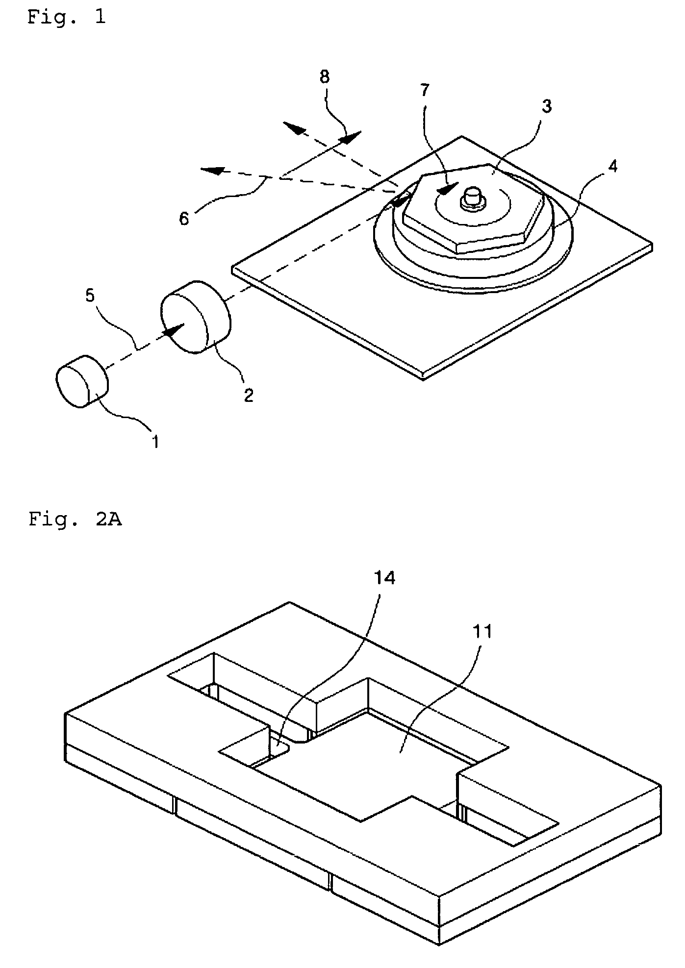
[0049]Now, a preferred embodiment of the present invention will be explained with reference to the accompanying drawings.

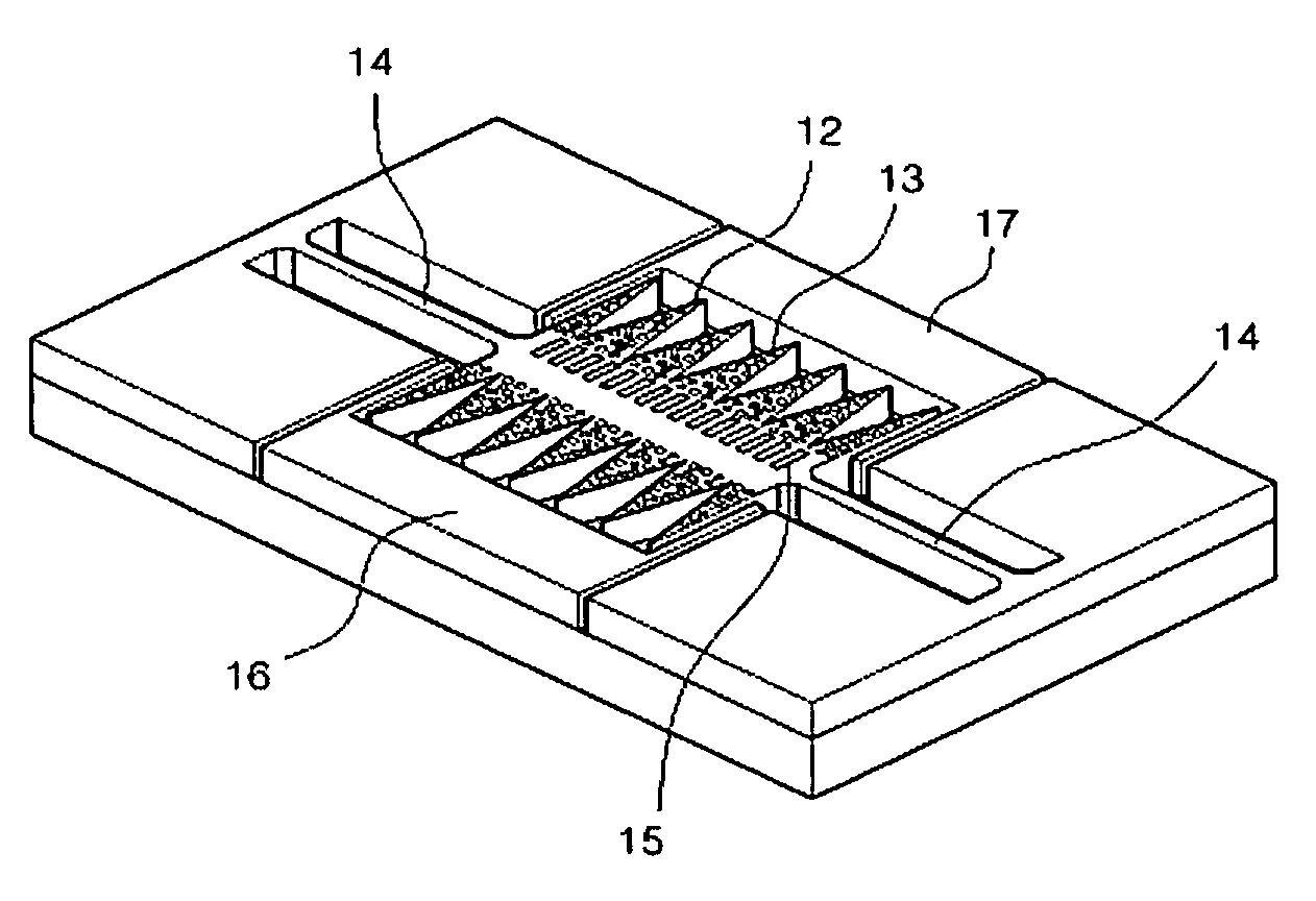
[0050]FIGS. 2A and 2B are perspective views illustrating an electromagnetic scanning mirror in accordance with an embodiment of the present invention. More particularly, FIG. 2A illustrates a reflective plane formed at a mirror plate, and FIG. 2B illustrates a frame structure formed at the mirror plate. Meanwhile, FIGS. 2A and 2B have no illustration of a magnetic force generator.

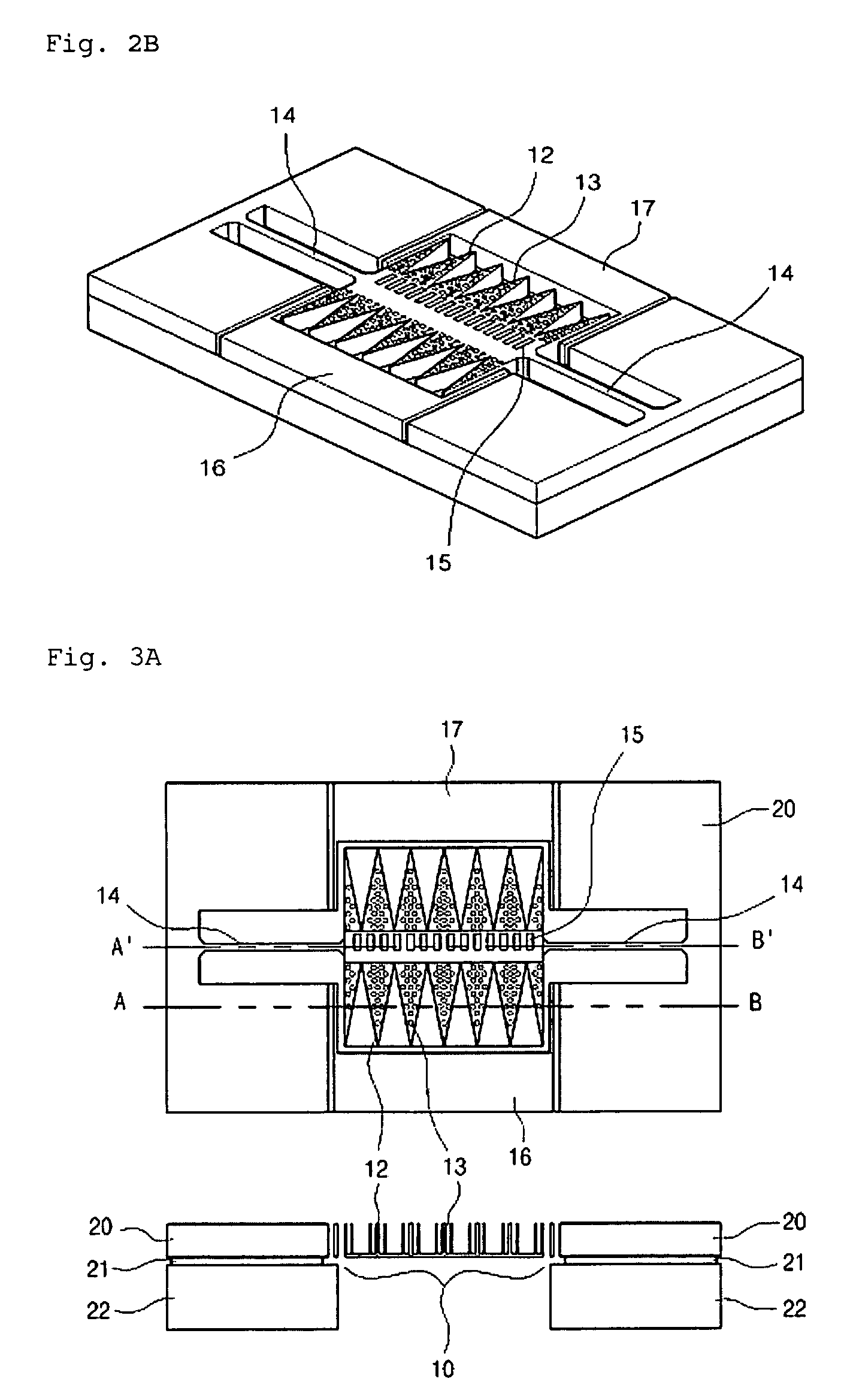
[0051]In the embodiment of the present invention, a scanning micro-mirror includes a mirror plate having a reflective plane 11 and a frame structure 12 attached to a rear surface of the reflective plane 11 to support the reflective plane 11, a substrate configured to surround the mirror plate, a pair of torsion bars 14 adapted to connect the mirror plate to the substrate, and a magnetic substance 15 formed on the frame structure 12. Also, a pair of regulation electrodes 16 and 17 are form...


PUM


Abstract

An electromagnetic scanning micro-mirror is provided with a magnetic field generator for supplying a magnetic field, a mirror plate having a reflective plane and a frame structure attached to a rear surface of the reflective plane, a substrate to surround the mirror plate, a pair of torsion bars to connect the mirror plate to the substrate, and a magnetic substance provided at the rear surface of the reflective plane of the mirror plate and adapted to generate a drive force by interacting with the magnetic field supplied from the magnetic field generator, wherein the mirror plate performs a rotation operation about the torsion bars, which define the rotating axis of the mirror plate, by use of the drive force generated from the magnetic substance.

Description

CROSS-REFERENCE TO RELATED APPLICATIONS[0001]Pursuant to 35 U.S.C. § 119(a), this application claims the benefit of earlier filing date and right of priority to Korean Patent Application No. 10-2005-0005126 filed on Jan. 19, 2005, which is hereby incorporated by reference herein in its entirety.BACKGROUND OF THE INVENTION[0002]1. Field of the Invention[0003]The present invention relates to an electromagnetic scanning micro-mirror.[0004]The scanning micro-mirror according to the present invention is applicable to laser printers, confocal microscopes, barcode scanners, scanning displays, and other various sensors, which are designed to scan a light beam, emitted from an optical source, to a predetermined region, such as a one-dimensional (i.e. line) or two-dimensional (i.e. plane) region for forming an image or reading position or image data.[0005]The micro-mirror according to the present invention is also applicable to optical switch devices for freely regulating a path of a reflecte...

Claims


Application Information

Patent Timeline
Patent Type & Authority Patents(United States)
IPC IPC(8): G02B26/08
CPCG02B26/085E06B3/9688E06B3/9648E06B3/9682
Inventor YEE, YOUNG-JOOJI, CHANG-HYEON
Owner LG ELECTRONICS INC
Why Eureka
Try Eureka