
Electronic appliance and fall detection method

a technology of electronic appliances and fall detection, applied in the field of electronic appliances, can solve the problems of hard disk drives, hard disk drives, and take about 100 milliseconds, and achieve the effect of reliably detecting a fall of electronic appliances and minimizing detection errors

Inactive Publication Date: 2008-01-29
SONY CORP
View PDF7 Cites 6 Cited by
  • Summary
  • Abstract
  • Description
  • Claims
  • Application Information

AI Technical Summary

Benefits of technology

This approach minimizes detection errors, prevents unnecessary retraction of the magnetic head, maintains continuous operation during carrying, and prolongs the service life of the hard disc drive by accurately distinguishing between falls and oscillations.

Problems solved by technology

Therefore, if the power supply is abruptly interrupted and the hard disc stops rotating, air is no longer drawn into the space between the magnetic head and the hard disc so that the magnetic head can come to contact the hard disc to consequently destroy the hard disc drive.
Meanwhile, if a portable electronic appliance falls while data are being recorded to or reproduced from the hard disc thereof, the magnetic head at a position located opposite to the hard disc collides with the hard disc to consequently destroy the hard disc drive.
However, with such an arrangement, it takes about 100 milliseconds from the time when it detects a fall to the time when the operation of retracting and saving the magnetic head is completed.
In view of these circumstances, it may be not permissible to spend 220 milliseconds for determining a fall for the purpose of retracting and saving the magnetic head with the above-described method.
As the operation of recording data to or reproducing data from the hard disc is interrupted, the user of the portable electronic appliance falls into trouble.
The number of times of utilization of the auto-retract feature is generally limited for such hard disc drives.
In other words, if a situation where the magnetic head is retracted from the position where it is located opposite to the hard disc because it is determined that the portable electronic appliance is falling although it is actually not falling, the service life of the auto-retract feature is curtailed to consequently make the hard disc drive vulnerable to destruction and allow the magnetic head to collide with the hard disc.
Thus, if it is so arranged as to detect a situation where the size of the synthetic acceleration vector is equal to 0 is detected to determine a fall of the portable electronic appliance, such an arrangement cannot detect a fall along a slope or a spinning fall and hence cannot prevent the hard disc drive from being destroyed.

Method used


Image

  • Electronic appliance and fall detection method
  • Electronic appliance and fall detection method
  • Electronic appliance and fall detection method

Examples


Embodiment Construction

[0032]Now, the best mode for carrying out the invention will be described in detail by referring to the accompanying drawings.

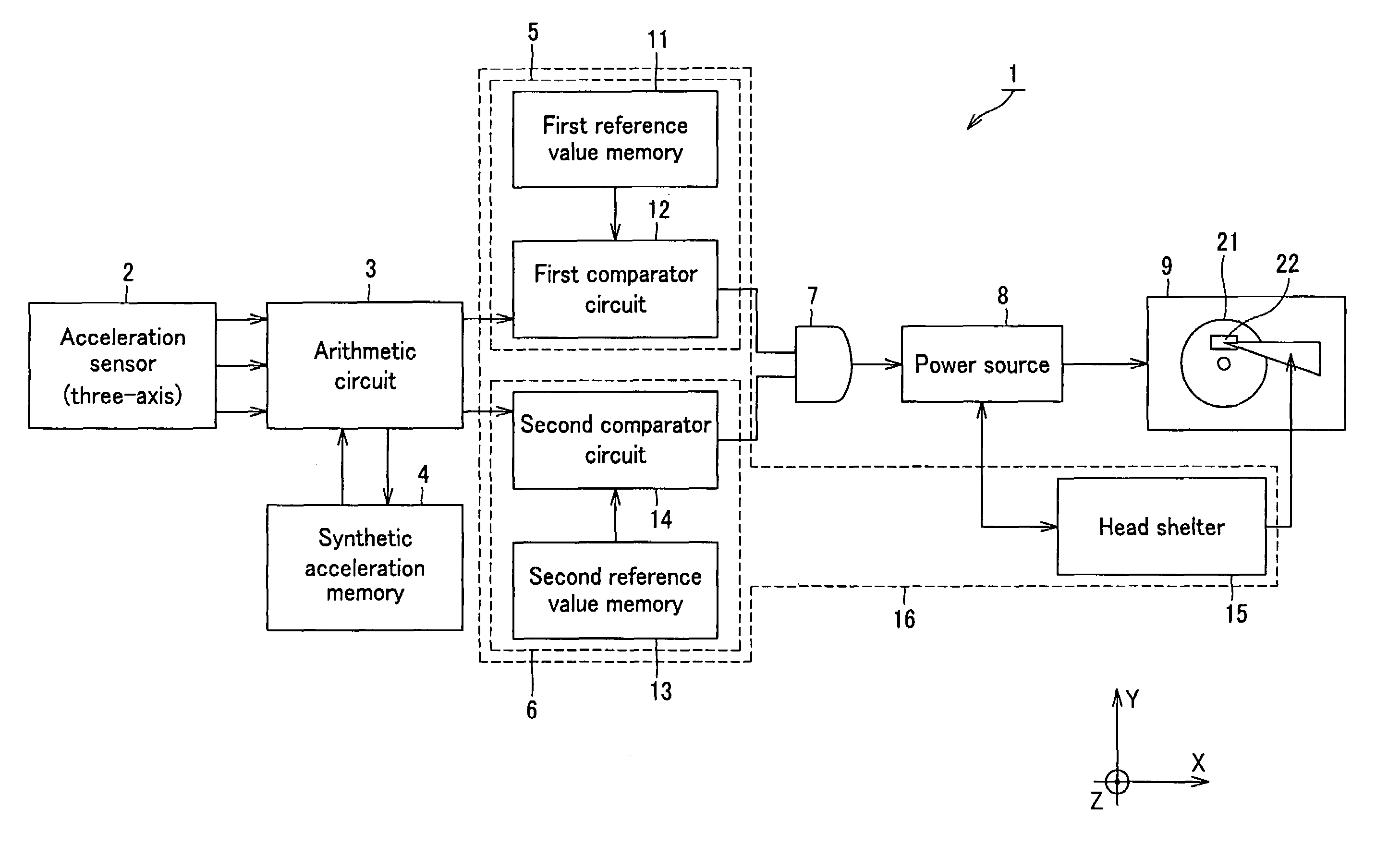
[0033]Referring to FIG. 3, an embodiment of electronic appliance according to the present invention, or electronic appliance 1, includes an acceleration sensor 2 that detects and outputs the acceleration in the X-direction in FIG. 3, the acceleration in the Y-direction that is orthogonal relative to the X-direction and the acceleration in the Z-direction that is orthogonal relative to both the X-direction and the Y-direction, an arithmetic circuit 3 that computationally operates according to the signal output from the acceleration sensor 2 and a synthetic acceleration memory 4 connected to the arithmetic circuit 3. The acceleration sensor 2 is an inertia sensor adapted to observe the component obtained by subtracting the gravitational acceleration component from the motional acceleration component for each of the X-, Y- and Z-directions as accelerations of th...


PUM

PropertyMeasurementUnit
timeaaaaaaaaaa
timeaaaaaaaaaa
clock timeaaaaaaaaaa

Abstract

In an electronic appliance, accelerations in X-direction, in Y-direction that is orthogonal relative to the X-direction and in Z-direction that is orthogonal relative to both the X-direction and the Y-direction are synthesized and the size of the synthetic acceleration vector formed by synthesizing the accelerations is detected, associated with the clock time of the detection and stored in a synthetic acceleration memory (4). A fall candidate is detected when the size of the synthetic acceleration vector is stabilized at a value close to a for a predetermined time period and clock time T1 that is associated with the synthetic acceleration vector that has a size equal to predetermined value b and closest to the clock time T1 when the fall candidate is detected is determined by retrieving the sizes of the synthetic acceleration vectors stored in the synthetic acceleration memory (4). Then, the stability of the sizes of the synthetic acceleration vectors from clock time T2 to clock time T1 that corresponds to the size of the synthetic acceleration vector that was stored earliest in the synthetic acceleration memory (4) is detected. Then, the electronic appliance is determined to be falling when a fall candidate is detected and the stability is found within a predetermined range.

Description

TECHNICAL FIELD[0001]This invention relates to an electronic appliance that can detect a fall that is taking place and prevent a hard disc drive thereof from being destroyed. The present invention also relates to a fall detection method that can accurately detect a fall that is taking place. The present invention also relates to a contents reproduction apparatus that can detect a fall that is taking place and prevent the hard disc drive thereof from being destroyed.[0002]The present invention contains subject matter related to Japanese Patent Application JP 2004-134327 filed in the Japanese Patent Office on Apr. 28, 2004 and Japanese Patent Application JP 2004-194643 filed in Japanese Patent Office on Jun. 30, 2004, the entire contents of which being incorporated herein by reference.BACKGROUND ART[0003]Existing portable electronic appliances are mostly equipped with a hard disc drive for the purpose of data storage capacity thereof. A hard disc drive includes a hard disc for storing...

Claims


Application Information

Patent Timeline
Patent Type & Authority Patents(United States)
IPC IPC(8): G11B21/02G11B19/04G01P15/18
CPCG01P15/18
Inventor ANDO, YOSHINORI
Owner SONY CORP
Learn More