Radio communication apparatus and method

Inactive Publication Date: 2008-01-29
KK TOSHIBA
View PDF13 Cites 9 Cited by
  • Summary
  • Abstract
  • Description
  • Claims
  • Application Information

AI Technical Summary

Benefits of technology

[0008]It is an object of the invention to improve the operating rate of a plurality of transmitting and

Problems solved by technology

Therefore, a received signal may have distortion that varies depending upon the place, time, etc.
However, in the above-described radio communication apparatus and method, since only a predetermined transmitting and re

Method used


Image

  • Radio communication apparatus and method
  • Radio communication apparatus and method
  • Radio communication apparatus and method

Examples


Example

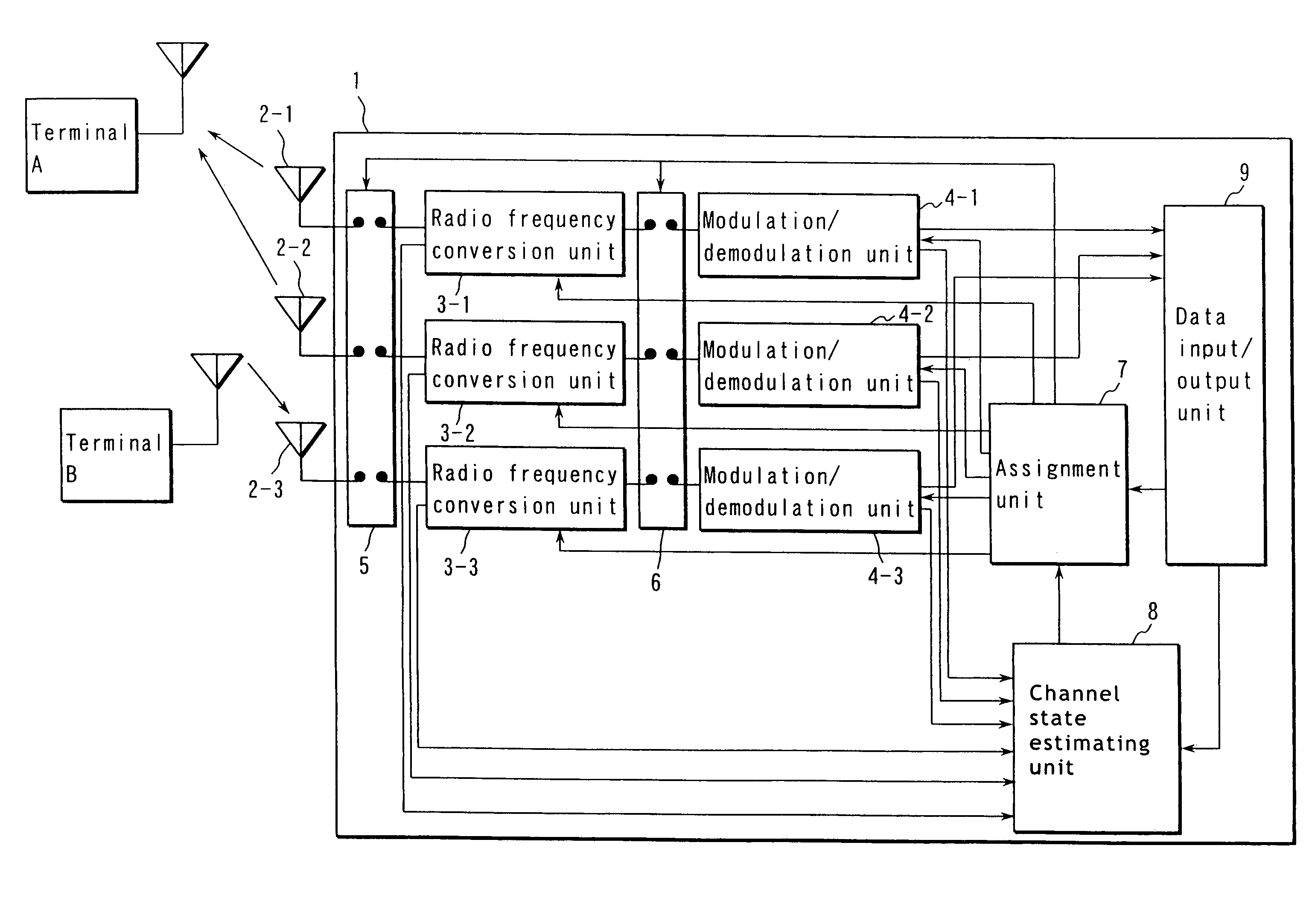
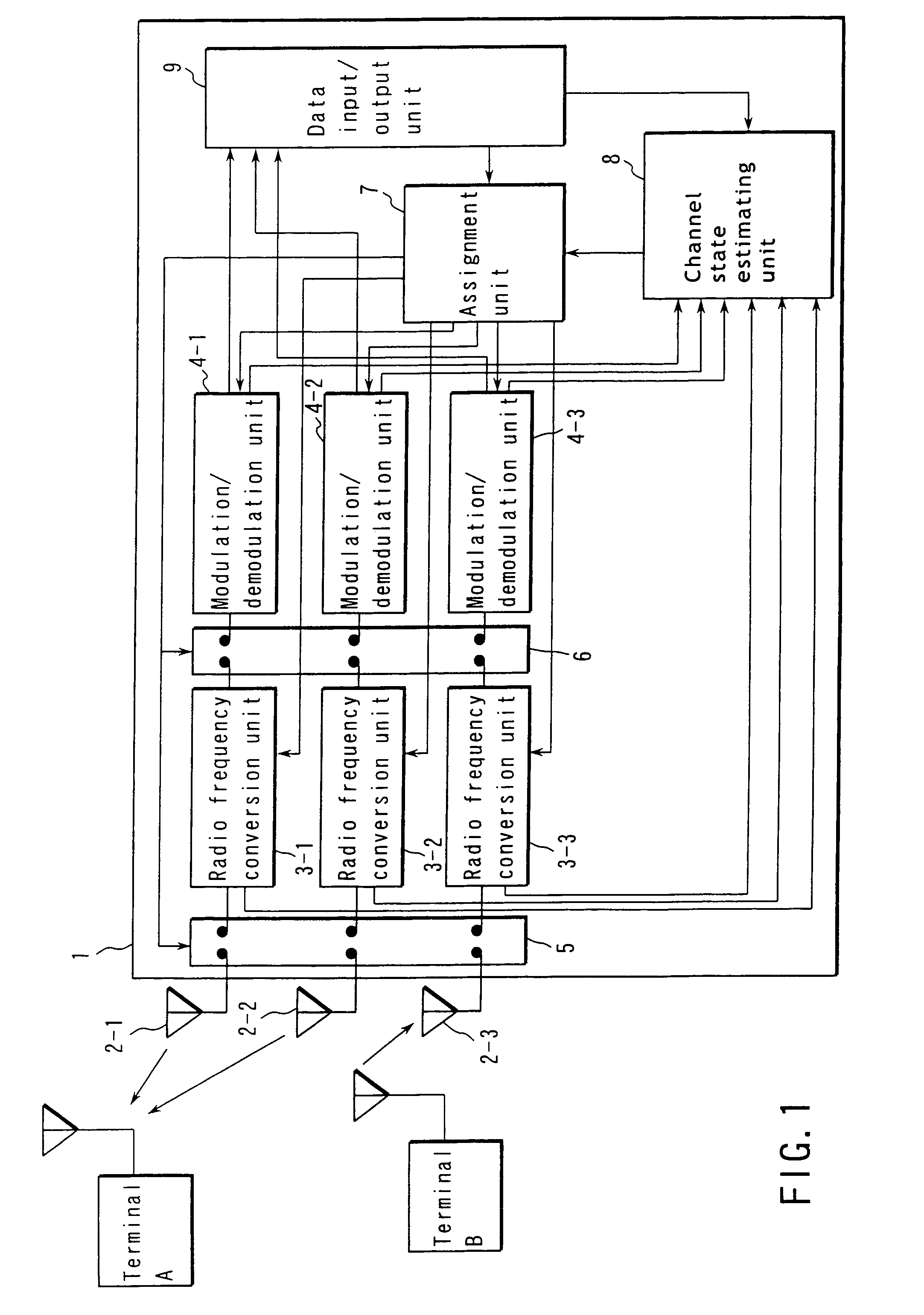
[0020]Embodiments of the invention will now be described in detail with reference to the accompanying drawings. FIG. 1 is a block diagram illustrating a radio communication apparatus according to an embodiment of the invention.

[0021]In this embodiment, a radio base station equipped with three antennas is assumed as a radio communication apparatus, and a description will be given of the case where terminals A and B are simultaneously connected to the base station. However, the radio communication apparatus of the embodiment of the invention may be a terminal.

[0022]A radio base station 1 shown in FIG. 1 has three transceiver units that enable the station to simultaneously transmit and receive signals. The base station 1 is provided with three antennas (2-1-2-3), three radio frequency conversion units (3-1-3-3) and three modulation / demodulation (modulation and demodulation) units (4-1-4-3). A switch group 5 is provided between the antennas (2-1-2-3) and radio frequency conversion units...


PUM


Abstract

In a radio communication apparatus having a plurality of transmitting and receiving functions that enable simultaneous signal transmission and reception, an arbitrary number of transmitting and receiving functions are assigned to another radio communication apparatus based on channel states.

Description

CROSS-REFERENCE TO RELATED APPLICATIONS[0001]This application is based upon and claims the benefit of priority from the prior Japanese Patent Application No. 2002-058200, filed Mar. 5, 2002, the entire contents of which are incorporated herein by reference.BACKGROUND OF THE INVENTION[0002]1. Field of the Invention[0003]The present invention relates to a radio communication apparatus having a plurality of transmitting and receiving (transmitting / receiving) functions, and a radio communication method employed therein.[0004]2. Description of the Related Art[0005]In radio communication systems, a transmitted signal can be received via various routes due to reflection by buildings. Therefore, a received signal may have distortion that varies depending upon the place, time, etc. Under such propagation circumstances, the influence of distortion is reduced by, for example, changing the transmission conditions such as the modulation method, encoding rate, etc., or by transmitting a signal us...

Claims


Application Information

Patent Timeline
IPC IPC(8): H04Q7/00H04B1/38H04B7/02H04L1/02H04B1/40H04B7/26H04B17/00H04W24/00H04W72/04H04W88/08
CPCH04L45/00H04W72/085H04W88/08H04W72/542
Inventor SATO, KAZUMITOSHIMITSU, KIYOSHI
Owner KK TOSHIBA
Why Eureka
Try Eureka