Systems and methods for generating an output oscillation signal with low jitter

a technology of output oscillation signal and output oscillation signal, which is applied in the field of integrated circuits, can solve the problems of achieve the effect of minimizing jitter and large variation at the output oscillation signal

Active Publication Date: 2008-01-29
SILICON LAB INC
View PDF46 Cites 28 Cited by
  • Summary
  • Abstract
  • Description
  • Claims
  • Application Information

AI Technical Summary

Benefits of technology

[0017]By adjusting the amplitude of the initial oscillation signal based upon the output oscillation signal, the amplitude of the output oscillation signal is held constant even if changes occur in a gain of a signal path through the first frequency multiplier, the filter, and the second frequency multiplier. Small variations in the gain of the signal path caused by, for example, process variations, power supply voltage fluctuations, and/or change in operating temperature accumulate and result in large variation at the outp

Problems solved by technology

Small variations in the gain of the signal path caused by, for example, process variations, power supply voltage fluctua

Method used


Image

  • Systems and methods for generating an output oscillation signal with low jitter
  • Systems and methods for generating an output oscillation signal with low jitter
  • Systems and methods for generating an output oscillation signal with low jitter

Examples


Embodiment Construction

[0027]The embodiments discussed herein are illustrative of one example of the present invention. As embodiments of the present invention are described with reference to illustrations, various modifications or adaptations of the methods and / or specific structures described may become apparent to those skilled in the art. All such modifications, adaptations, or variations that rely upon the teachings of the present invention, and through which these teachings have advanced the art, are considered to be within the spirit and scope of the present invention. Hence, these descriptions and drawings should not be considered in a limiting sense, as it is understood that the present invention is in no way limited to only the embodiments illustrated.

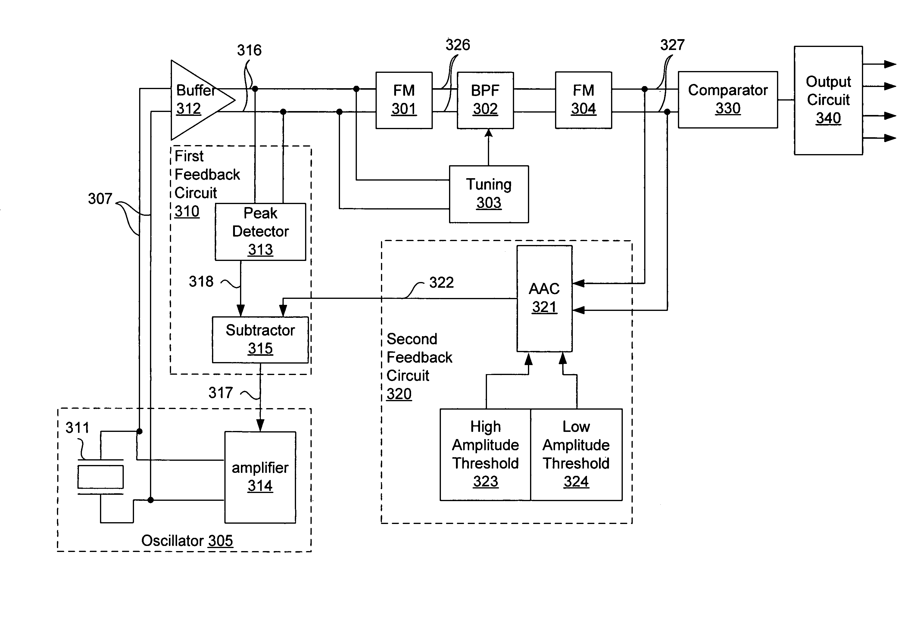
[0028]FIG. 3A illustrates a block diagram of a circuit for generating an output oscillation signal with low jitter in one embodiment of the invention. An oscillator 305 comprises a resonator 311 and an amplifier 314 to generate an initial oscillati...


PUM


Abstract

A circuit for generating an output oscillation signal with low jitter includes an oscillator to generate an oscillation signal at an initial frequency based upon a control input to vary an amplitude of the oscillation signal. A first frequency multiplier multiplies the oscillation signal to result in a first signal with first frequency and first undesired frequency components. A filter minimizes the first undesired frequency components of the first signal. A second frequency multiplier multiplies the first signal to result in the output oscillation signal with second frequency and second undesired frequency components. A second feedback circuit compares a predetermined range and at least one of the first signal and the output oscillation signal to result in a reference value. A first feedback circuit varies the control input based upon a comparison between the reference value and the amplitude of the oscillation signal to minimize the second undesired frequency components.

Description

CROSS-REFERENCE TO RELATED APPLICATIONS[0001]This application claims the benefit of Provisional Patent Application Ser. No. 60 / 478,628, filed Jun. 13, 2003, entitled “A Semiconductor Integrated Circuit for Frequency Multiplication,” which is hereby incorporated by reference. This application is also related to co-pending U.S. patent application Ser. No. 10 / 856,202, filed May 28, 2004, entitled “Oscillator with Variable Reference,” now U.S. Pat. No. 7,098,753 issued on Aug. 29, 2006, which is hereby incorporated by reference. This application is also related to co-pending U.S. patent application Ser. No. 10 / 857,241, filed May 28, 2004, entitled “Systems and Methods for Tuning the Operating Frequency of a Crystal,” now abandoned, which is hereby incorporated by reference.BACKGROUND OF THE INVENTION[0002]1. Field of the Invention[0003]This invention relates generally to integrated circuits, and more specifically to systems and methods for generating an output oscillation signal with lo...

Claims


Application Information

Patent Timeline
IPC IPC(8): H04J3/06
CPCH03K5/08H03K5/15013H03K5/1565
Inventor MILLER, RICHARDDUMITRESCU, GABRIEL-GHEORGHEOPRIS, ION E.
Owner SILICON LAB INC
Why Eureka
Try Eureka