
Combined padlock housing and acoustic notification device

a combination padlock and acoustic notification technology, which is applied in the field of padlock housings, can solve the problems of theft or trespassing to tamper with the padlock, theft of, or tampering with, the property

Inactive Publication Date: 2008-02-05
MILLER JOSEPH F
View PDF17 Cites 11 Cited by
  • Summary
  • Abstract
  • Description
  • Claims
  • Application Information

AI Technical Summary

Benefits of technology

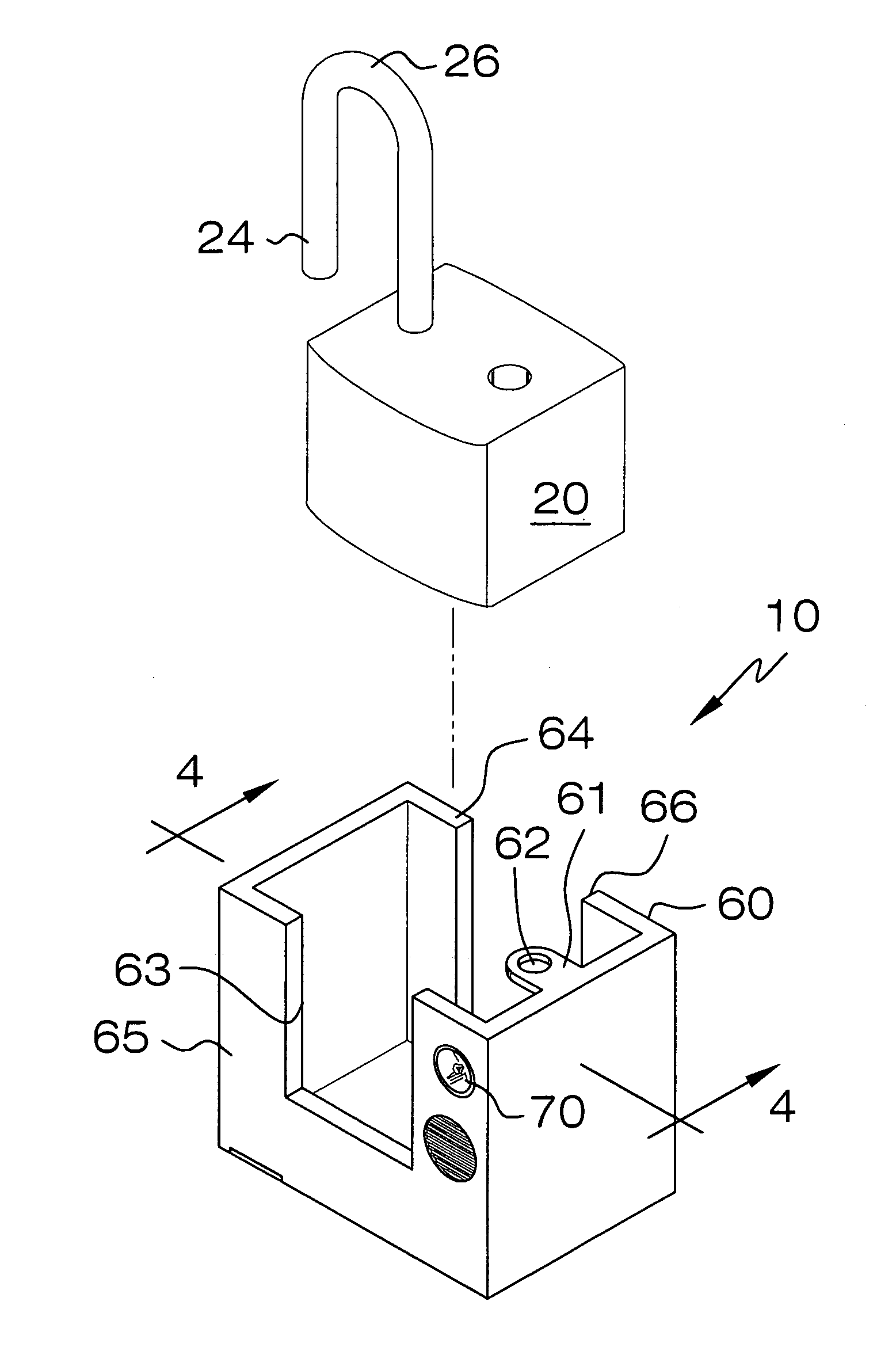
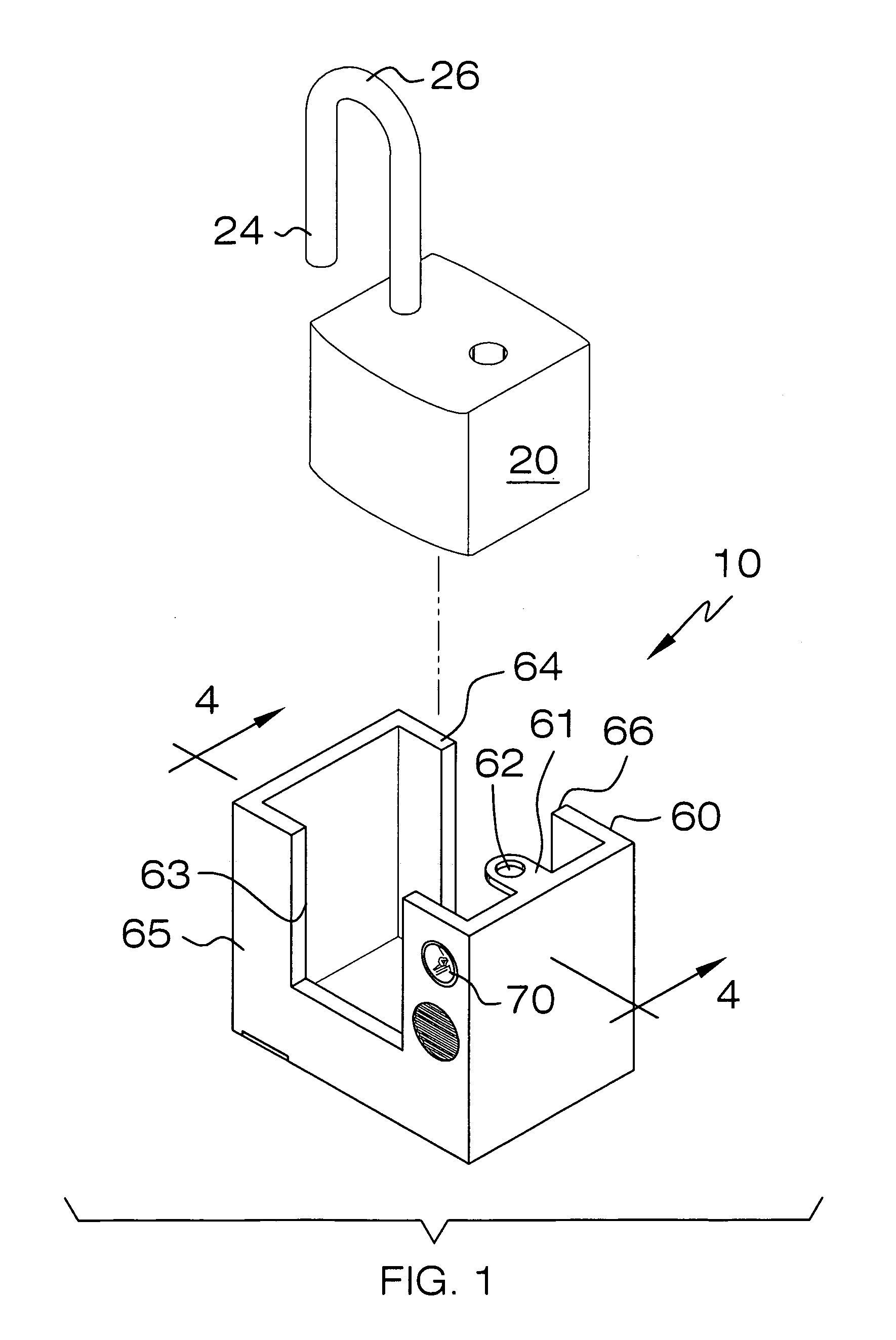
[0012]Another one of the walls is provided with a notch formed therein. Such a notch is situated subjacent the aperture such that the shank slidably adjoins the notch when interfitted through the aperture. The shank maintains a static relationship with the padlock housing when the shank is passed through the aperture and engaged with the existing padlock to a closed position. The shank is exposed above the padlock housing during operating conditions for allowing the user to readily access the shank during closed positions.
[0013]Notably, audio mechanism for playing an audio file when the shank is biased to an open position is also provided. The audio mechanism is housed within the padlock housing in such a manner that the operator cannot tamper or alter the audio mechanism without dismantling the padlock housing walls. The audio mechanism is uploaded with a predetermined quantity of audio files which can be downloaded and transferred to a portable electronic device via conventional communication links such as a USB cord or flash memory device, for example. A visual notification emitter is also provided for illuminating a predetermined lumen rating when the shank is biased to the open position. Such an emitter preferably includes a conventional LED provided with an associated power driver for regulating voltage input transferred thereto. The driver may generate a sequential and oscillating voltage input for the LED such that the LED is caused to blink, for example. Alternately, the driver may provide a continuous voltage input to the LED for causing the LED to provide a steady luminescence when the shaft is biased to the open position.
[0015]In a preferred embodiment, the audio mechanism includes a signal interface circuit receiving the power input signal. Such an interface circuit is electrically and directly coupled to the trigger mechanism. The audio mechanism further includes an audio play-back device and a memory electrically coupled thereto. The audio play-back device is electrically and directly coupled to the signal interface circuit wherein the power input signal instructs the audio play-back device to access and play the one audio file. A speaker is electrically and directly coupled an amplifier and the amplifier is directly coupled to the audio play-back device. The amplifier receives the output signal and increases a voltage level associated with the output signal such that the audio file can be played back at a sufficient volume for notifying the operator that the existing padlock is biased to the open position.
[0017]A plurality of electrically conductive contacts are selectively engageable with the actuator arm when the shank is removed from the aperture and thereby disengaged from the ball bearing. An internal power supply source has positive and negative terminals electrically mated to the audio mechanism and electrically mateable with the contacts for closing a conductive path when the shank is removed from the aperture to thereby power the audio device. Notably, the spring member is compressible along a horizontal axis for allowing the shank to freely slide along the vertical axis.

Problems solved by technology

It is not uncommon, however, for someone intent on theft or trespassing to tamper with the padlock in an attempt to open it in an unauthorized manner, either by severing the shackle or by forcing it into an open position.
This may also lead to theft of, or tampering with, the property that the lock is intended to protect.

Method used


Image

  • Combined padlock housing and acoustic notification device
  • Combined padlock housing and acoustic notification device
  • Combined padlock housing and acoustic notification device

Examples


Embodiment Construction

[0027]The present invention will now be described more fully hereinafter with reference to the accompanying drawings, in which a preferred embodiment of the invention is shown. This invention may, however, be embodied in many different forms and should not be construed as limited to the embodiment set forth herein. Rather, this embodiment is provided so that this application will be thorough and complete, and will fully convey the true scope of the invention to those skilled in the art. Like numbers refer to like elements throughout the figures. Prime and double notations refer to alternate embodiments of like elements.

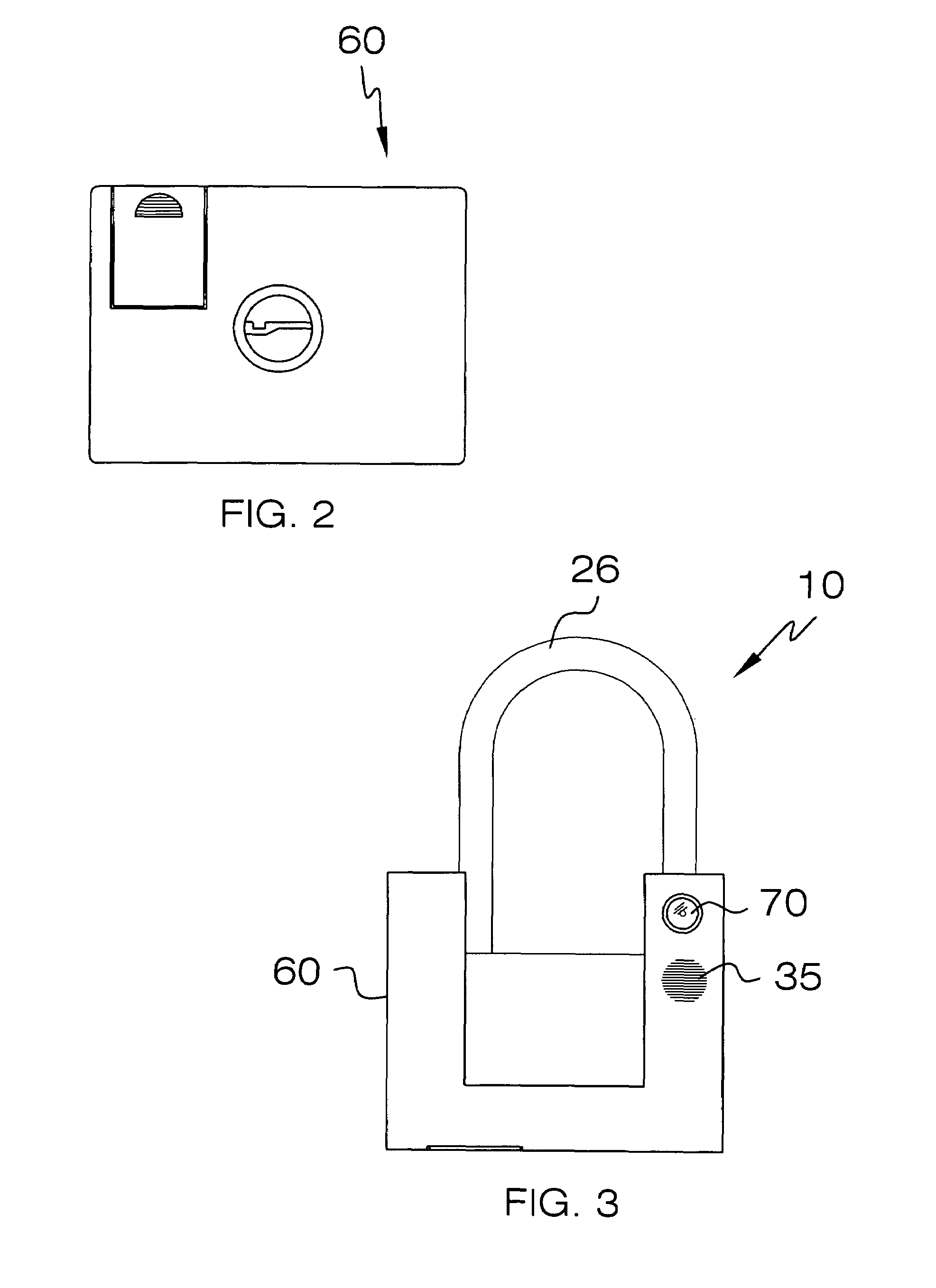
[0028]The device of this invention is referred to generally in FIGS. 1-7 by the reference numeral 10 and is intended to provide a combined padlock housing and acoustic notification assembly. It should be understood that the assembly 10 may be employed with various padlocks and, therefore, should not be construed as having limited use with any one particular padlock av...


PUM


Abstract

The padlock housing assembly includes a padlock housing having monolithically formed walls for cradling an existing padlock therein. A top one of the walls is provided with an annular aperture for receiving a U-shaped shank of an existing padlock therethrough. The shank maintains a static relationship with the padlock housing when the shank is passed through the aperture and engaged with the existing padlock to a closed position. An audio mechanism is included for playing an audio file when the shank is biased to an open position and is housed within the cavity. At least one LED is also provided for emitting a predetermined luminescence when the shaft is biased to the open position. A trigger mechanism transmits a power input signal to the audio mechanism when the shank is biased to the open position. The triggering mechanism is operably engaged with the shank.

Description

CROSS REFERENCE TO RELATED APPLICATIONS[0001]Not Applicable.STATEMENT REGARDING FEDERALLY SPONSORED RESEARCH OR DEVELOPMENT[0002]Not Applicable.REFERENCE TO A MICROFICHE APPENDIX[0003]Not Applicable.BACKGROUND OF THE INVENTION[0004]1. Technical Field[0005]This invention relates to padlock housings and, more particularly, to a combined padlock housing and acoustic notification device for providing audible and visual warning signals when a padlock is biased to an open position.[0006]2. Prior Art[0007]Generally, a padlock comprises a body and a shackle having a pair of legs. The shackle is mounted for reciprocal movement relative to the body between a closed first position and an open second position. Located within the body is a latch for engaging one leg of the shackle when the shackle is in its closed position, preventing movement of the shackle to its open position. In order to move the shackle from its closed to its open position, the latch must be disengaged, and the padlock incl...

Claims


Application Information

Patent Timeline
IPC IPC(8): E05B67/02G08B13/00
CPCE05B67/38E05B45/12Y10T70/489
Inventor MILLER, JOSEPH F.
Owner MILLER JOSEPH F
Learn More