Particle matter sampling method and sampler with a virtual impactor particle concentrator

a particle concentrator and particle matter technology, applied in the field of particle matter sampling methods and samplers with virtual impactor particle concentrators, can solve the problems of increased hospital admissions, euthanasia, inflammation and damage to the lungs, paucity of information about specific biological mechanisms, and reduced sample quality, so as to reduce air turbulence and finer cut

Inactive Publication Date: 2008-02-05
ENVIRONMENTAL PROTECTION AGENCY US
View PDF4 Cites 23 Cited by
  • Summary
  • Abstract
  • Description
  • Claims
  • Application Information

AI Technical Summary

Benefits of technology

[0014]In the acceleration tube, the conical section should join the inlet and outlet straight cylinder sections at an angle of 45° or less in order to minimize air turbulence and obtain a finer cut between fine and coarse fractions.

Problems solved by technology

They can cause breathing and respiratory symptoms, irritation, inflammation and damage to the lungs.
These effects can result in increased hospital admissions, emergency room visits, absences from school or work, and restricted activity days.
Despite the growing evidence of particulate-related health effects, the paucity of information about specific biological mechanisms remains a critical missing link.

Method used


Image

  • Particle matter sampling method and sampler with a virtual impactor particle concentrator
  • Particle matter sampling method and sampler with a virtual impactor particle concentrator
  • Particle matter sampling method and sampler with a virtual impactor particle concentrator

Examples


Embodiment Construction

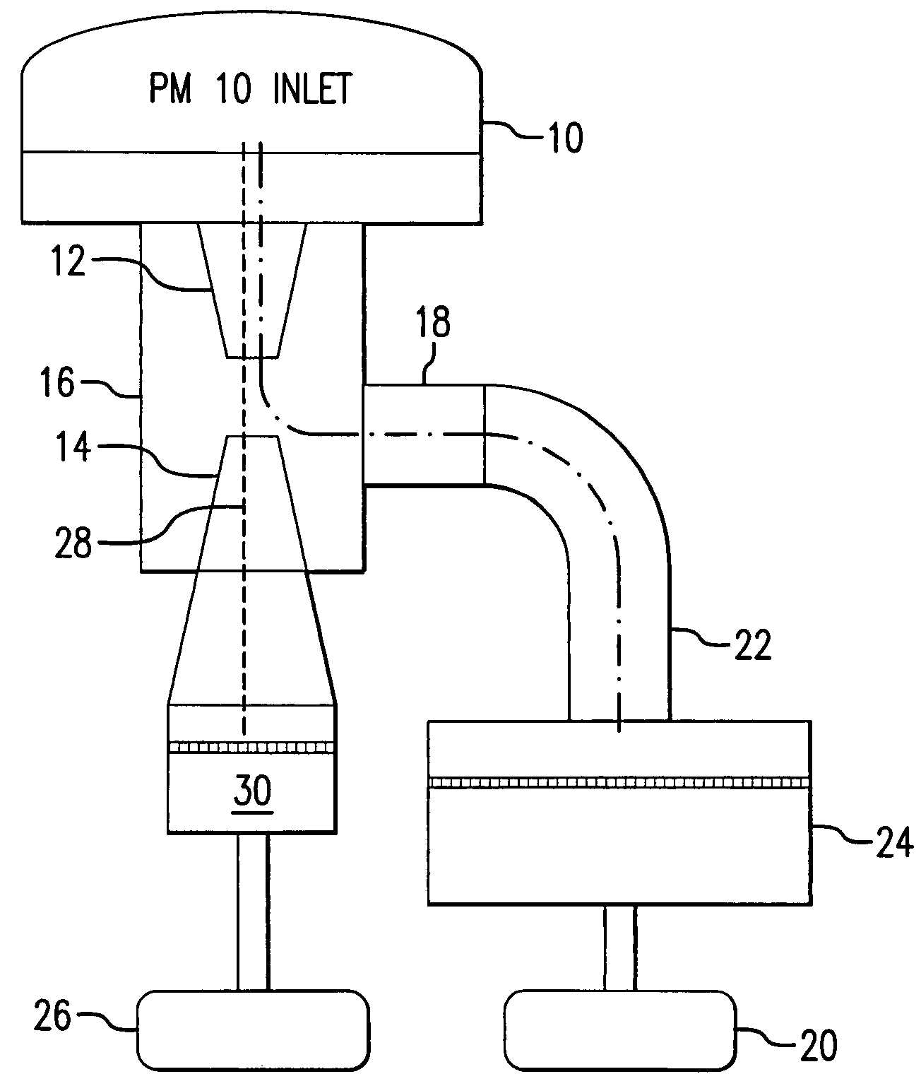
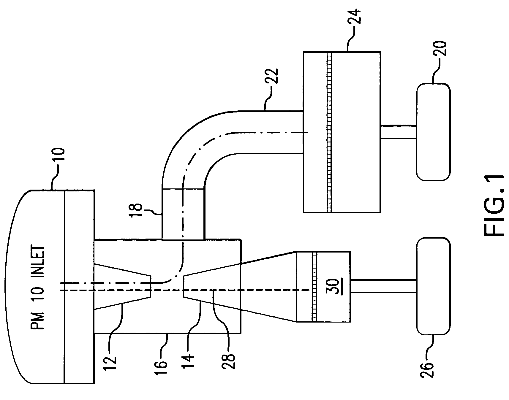
[0026]Preferred embodiments of the invention will now be described with reference to the accompanying drawings. As used herein “flow rate” means volumetric flow rate. Particle size, expressed in microns, should be understood as aerodynamic diameter, as conventionally used in the art.

[0027]FIG. 1 shows a preferred embodiment as including a PM10 separating device 10, an acceleration tube 12, a collection tube 14 and a housing 16 surrounding the acceleration tube 12 and collection tube 14. The housing 16 has a side-wall nozzle 18 through which a major portion of the sampled ambient air is drawn by a large volume suction device, e.g., the suction side of an air pump 20 with volumetric flow control. The fine particle cut 22, i.e., 2-3 microns and smaller, is separated and collected in a fine particulate collector, e.g., filter and filter holder 24. A small volume suction device, e.g., the inlet side of air pump 26 with volumetric flow control, draws a minor portion of the sampled ambient...


PUM

PropertyMeasurementUnit
anglesaaaaaaaaaa
anglesaaaaaaaaaa
angleaaaaaaaaaa

Abstract

An apparatus for sampling ambient air to obtain coarse and fine fractions of particulate matter includes a single acceleration tube and a collection tube coaxially arranged along a central axis with a gap between facing distal ends thereof within a range of d / D1 of 1 to 2, wherein d is the distance or gap between the distal ends and D1 is the inside diameter of the outlet at the distal end of the acceleration tube. A housing surrounding the acceleration and concentration tubes is provided with a side-wall nozzle connected to a suction device for drawing a major portion of the sampled ambient air therethrough and for separation of particulate matter, as a fine fraction, from that major portion. A second suction device draws a minor portion of the sampled ambient air, containing the coarse fraction of the particulate matter, in a straight path approximating the central axis, through the acceleration tube and through the collection tube for passage through a filter for separation of the coarse fraction of particulate matter. The ratio of the flow rates of the major and minor portions of the sampled ambient air is adjusted to provide a cutpoint within the range of 2-3 microns. The apparatus is preferably operated with a flow rate for the sampled ambient air within the range of 900-1200 liters per minute.

Description

BACKGROUND OF THE INVENTION[0001]1. Field of the Invention[0002]The present invention is directed to the sampling of ambient air and separation and collection of particulate matter fractions (PM) from the sample.[0003]2. The Related Art[0004]Airborne particulate matter, known as PM, is one of the major components of smog. PM includes microscopic particles in the air that are divided into two size ranges: PM2.5 and PM 10. PM2.5 refers to “fine” particles less than 2.5 micrometers (microns) in size about 1 / 20th the width of a human hair. Likewise, PM10 refers to particles less than 10 microns in size. As used herein,“coarse” has reference to a PM fraction 2.5-10 microns in size.[0005]PM can be released directly to the atmosphere from such sources as industrial smokestacks, automobile tailpipes, wood burning and road dust, to mention a few. PM can also form in the atmosphere from chemical reactions involving other pollutants such as sulphur dioxide (SO2), nitrogen oxides (NOX), ammonia...

Claims


Application Information

Patent Timeline
Patent Type & Authority Patents(United States)
IPC IPC(8): G01N1/22
CPCG01N15/0255G01N15/0272G01N2015/0261
Inventor SOLOMON, PAUL A.SIOUTAS, CONSTANTINOS
Owner ENVIRONMENTAL PROTECTION AGENCY US
Why Eureka
Try Eureka